This is the working document for developing Ainekio’s gait. It begins with
the original eight-servo robot, then compares that motion baseline with the
radically different twelve-servo linkage design. New calculations, experiments,
and physical results will be recorded here as dated entries.
The latest motion entry replaces
model-requested continuation with finite target programs. It records the new
339-example model, simulated event corrections, a supported stretch with nine
verified targets, and the calibration differences still to resolve.
October 26: targets, measured arrival and Stand training#
Freestyle now has an editable
motion library and compact target generation. Joint, foot and body targets use
requested speed; the P4 waits for fresh shaft arrival rather than assuming that
elapsed time means completion. The existing gait solver remains in use.
The latest 1,261-example Stand continuation improves reference agreement but
reaches the geometric goal in only one of three offline starting cases. Reviewed
brisk-lift and rear-sway trials are recorded separately. The 650 g body and
support-stand entry covers
current dimensions and supported firmware trials. Earlier walking comparisons
remain below; no new floor-walking improvement is claimed here.
October 21: physical comparisons and learning during use#
The latest walking report follows
loaded October 19 trials and the October 20 host learning loop. The earlier
forward-Walk comparison reduced estimated linkage tracking error by 2.84%,
with mixed pitch and distance results. The owner later reported that forward,
backward, turns and Run remained unsatisfactory. The newer automatic candidate
comparison did not promote an improved policy.
Recording, separate Walk/Run comparisons, experimental depth-based progress and
learning history now operate through Body Control. Missing measurements remain
unknown; usable evidence of poor motion still counts. Measured camera accuracy,
repeatable gait quality and autonomous return-to-start remain open.
The latest servo-feedback report
explains the fourth-wire modification, multiplexer and twelve saved calibration
curves. October 16 floor trials still showed sagging, foot drag and weak motion
at low stride; no gait winner was established. Unloaded servo agreement is now
measured, but assembled standing and walking remain to qualify. The
gallery separates physical trials from Blender studies.
Earlier physical baseline, October 8: the robot can stand, walk and respond to commands.
This is the owner’s physical result. The carapace is not attached, and Active
Operator has not been tested. Exact installed revisions and measured walking
performance remain to document; the earlier offline reach/travel questions
are preserved in their dated entries.
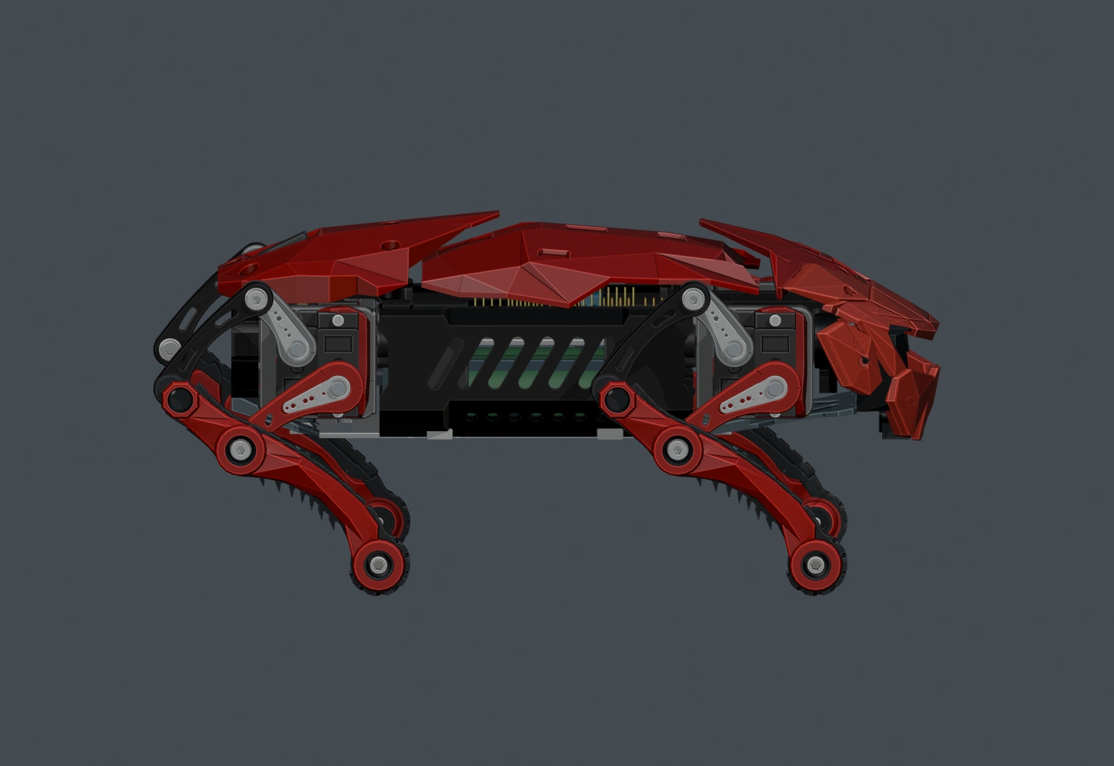
September 23 Blender showcase: 33 chapters, 4 minutes 10 seconds, 2× playback, no audio. This shows the red body and the preceding motion library. The later reviewed Worm, Shrug, Play Dead, Lay Down and six-direction Crab changes are described in the September 24 entry; they are not all shown in this export.
September 15, 2026 — Establishing the movement baseline#
At this entry’s date, the prepared material covered movement ranges and
kinematic groundwork; the V2 gait had not yet been calculated. “Current” in
this entry refers to its September 15 source snapshot.
1. What the eight-servo Ainekio currently commands#
V1 has two actuators per leg and eight stored joint channels. Its motion
library contains 38 named assets, including standing, walking, turning,
and expressive poses. The following values were extracted from the current
motions-v1.json and checked against all 38 packed .amot files used by the
firmware asset loader.
There are three different quantities to keep track of: the controller’s
accepted angle range, the angles actually used by a motion, and the assembled
leg’s physical travel. The first two are available in these files. They do not
supply a measured foot workspace or the mechanical stops of every V1 joint.
The V1 software accepts logical angles from 0° to 180°. The checked S3
configuration uses 100% motion range. Before output, each logical target is
mapped through the joint’s calibrated center and direction and checked against
its calibrated minimum and maximum. With the default center of 90° and no
inversion, the mapping is unchanged; installed calibration can differ.
All columns below use V1 logical degrees. “All motions” is the minimum and
maximum explicit target across the 38 assets, including emotes. “Walk” is
walk_forward, including its setup and final stand pose. These are separate
target envelopes, not a set of limits to send to the new body.
ID · joint
All motions
Stand
Walk
Walk excursion from stand
0 · R1
85–180°
135°
90–180°
−45 to +45°
1 · R2
0–100°
45°
45–100°
0 to +55°
2 · L1
0–95°
45°
0–90°
−45 to +45°
3 · L2
90–180°
135°
90–135°
−45 to 0°
4 · R4
0–180°
0°
0–45°
0 to +45°
5 · R3
0–180°
180°
135–180°
−45 to 0°
6 · L3
0–180°
0°
0–45°
0 to +45°
7 · L4
0–180°
180°
135–180°
−45 to 0°
The unusual R4-before-R3 order is the actual version-1 channel map.
The all-90° rest/neutral command is also different from the stand pose above.
Neither establishes the neutral geometry of V2.
The existing forward pattern has six repeated target groups. A joint omitted
from a group keeps its preceding target. The group labels below preserve the
source channel names rather than assigning them to V2 parts.
Group
Changed V1 targets, logical degrees
Stored duration
1
R3 = 135; L3 = 0
140 ms
2
L4 = 135; L2 = 90; R4 = 0; R1 = 180
180 ms
3
R2 = 45; L1 = 90
140 ms
4
R4 = 45; L4 = 180
140 ms
5
R3 = 180; L3 = 45; R2 = 90; L1 = 0
180 ms
6
L2 = 135; R1 = 90
140 ms
One repetition totals 920 ms. The stored walk_forward asset contains
five repetitions, a 180 ms setup, and a 160 ms final stand frame: 4,940 ms
across 32 frames. This is a timed command sequence, not a measurement of
distance covered or foot contact duration.
V1 asset
Repeated six-group pattern
Pattern repetitions
Complete stored asset
walk_forward
920 ms
5
4,940 ms · 32 frames
walk_slow
1,840 ms
3
6,740 ms · 21 frames
run
720 ms
6
5,180 ms · 39 frames
The two cadence variants keep the forward-walk target envelope. Their complete
durations include their own entry and exit frames; a longer total asset does
not necessarily mean a slower repeated pattern. The name run describes the
stored command and does not establish an airborne running gait.
The checked S3 profile interpolates addressed joints with cubic easing on a
20 ms update tick, using a transition window of at most 300 ms within each
frame. That playback behavior matters when interpreting the older sequence
data. It does not supply V2’s required timing or loaded servo speed.
V2 has three actuators per leg, but its change is larger than adding a sideways
joint to the old pose arrays. Two planar motors control a carrier and a
linkage-driven lower assembly; a third rotates the leg sideways at the
shoulder. The lower assembly’s angle is not equal to its driving servo’s
angle. The new gait needs a geometric conversion between desired foot
positions and all three actuator angles.
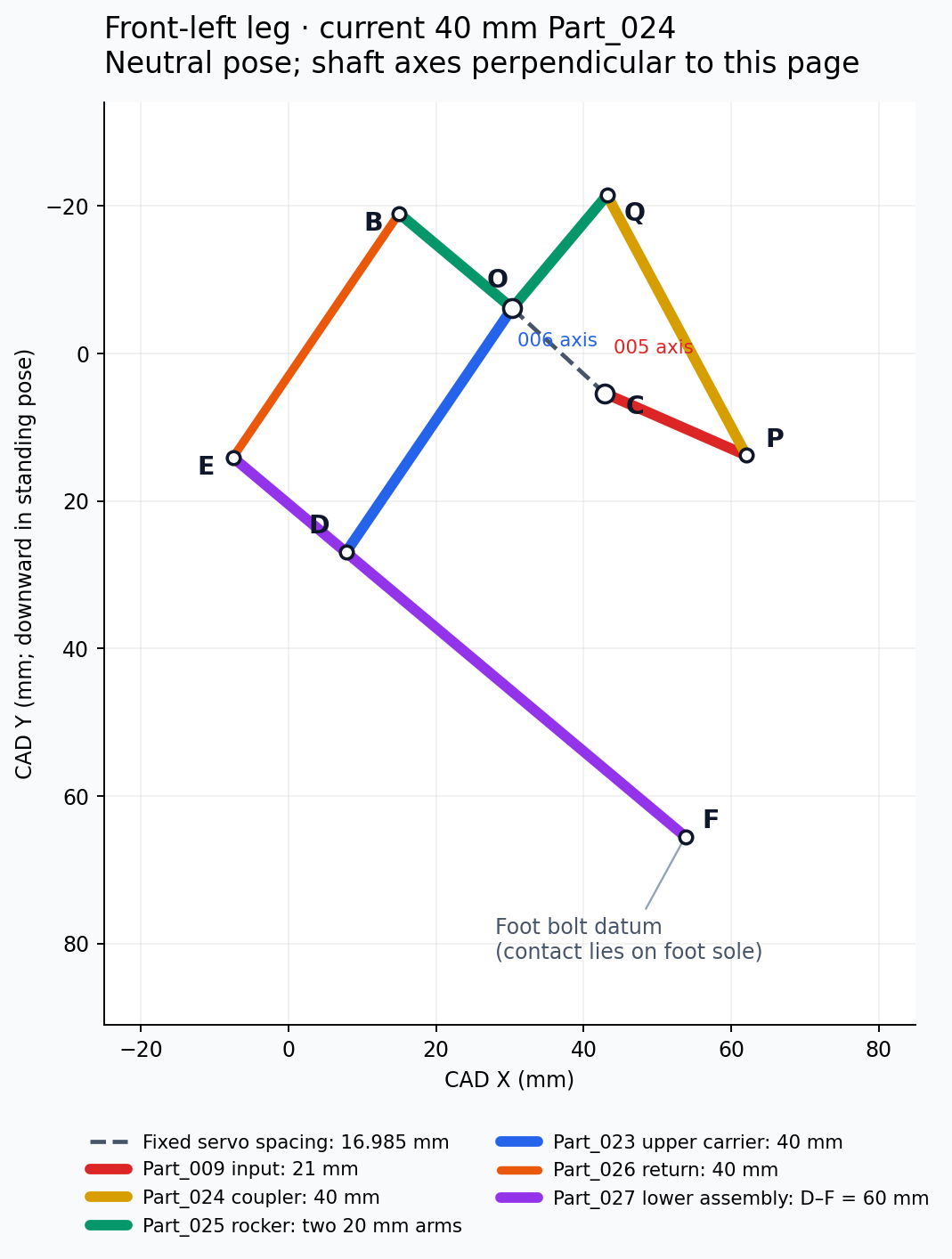
Supplied September 15 mechanism diagram. Dimensions join pivot centers. F is
the foot attachment-bolt datum, not the point where the sole touches ground.
Part_005 drives the Part_009 crank and Part_024 coupler
Change from the current frame-1 horn position, about Blender +Z
beta
Passive Part_025 rocker and lower-assembly orientation
Change from frame 1, about Blender +Z; determined by theta
h
Part_002 shoulder swivel
Change from frame 1, about Blender +X
Part_023 and Part_025 share pivot O but rotate independently. Part_006 drives
the carrier; Part_025 follows the other motor through C–P–Q–O. Holding
theta fixed holds the lower assembly’s planar orientation while alpha
moves its upper attachment. The bend between the upper and lower segments
therefore changes with beta − alpha, plus the neutral geometry offset.
Pivot pair
Front-left dimension
Function
O–C
16.9853 mm
Fixed spacing between the two planar servo axes
C–P
21 mm
Input crank, Part_009
P–Q
40 mm
Current front-left Part_024 coupler
O–Q and O–B
20 mm each
Two arms of the Part_025 rocker
O–D and B–E
40 mm each
Carrier and return link
D–E
20 mm
Lower assembly’s return-link arm
D–F
60.0003 mm, nominally 60 mm
Distal pivot to foot-bolt datum
The saved assembly is currently a mixture of revisions:
Blender leg label
Part_024 pivot spacing
Motion evidence in this handoff
FL
40.0000 mm
505 saved frames covering separate planar sweeps
FR
24.6395 mm
Neutral assembly only
RL
24.6395 mm
Neutral assembly only
RR
24.6395 mm
Neutral assembly only
These are the literal Blender labels. Their correspondence to physical
front/back and hardware channels still needs confirmation. In the handoff’s
chosen coordinate frame, the objects labeled FL/FR are at negative longitudinal
coordinates. The journal retains that convention.
The 40 mm FL linkage is a later revision than the short-link fit discussed in
the printed-leg update. It must not be
silently applied to the other three legs. The replacement also re-clocked the
FL input horn by 46.4615°; the new theta = 0 already includes that change.
3. Theoretical movement ranges of the current FL leg#
The prepared handoff records the following single-actuator animation
intervals. They describe the modeled range study; they are not newly proven
absolute maximum travel or measured physical limits. All angles are relative
to the saved neutral pose, with the definitions above.
Motion
Interval
Angular span
Other inputs held fixed
Upper-carrier input alpha
−53.4000 to +67.4000°
120.8000°
theta = 0, h = 0
Linkage-crank input theta
−51.9533 to +51.6303°
103.5837°
alpha = 0, h = 0
Resulting lower orientation beta
−48.1011 to +25.8715°
73.9727°
Output of the theta sweep
Shoulder input h
Not established
Not established
Shoulder was not animated
The beta row is a passive output, not a fourth actuator or a direct measure
of the knee bend across all carrier positions. Likewise, subtracting the
extreme alpha and beta values would combine separate tests and would not
establish a usable bending range.
The replacement’s saved verification reports no new modeled contacts across
those frames relative to the existing mating overlaps, using a 0.03 mm³
added-overlap criterion. The two input intervals do not define a proven
collision-free rectangle. Combined carrier, crank, and shoulder motion still
needs checking against the links, screws, housings, chassis, other legs, and
ground. No sweep limits for FR, RL, or RR are established by this package.
Evaluating the supplied forward-kinematics function at a few FL crank angles
gives the following lower-assembly changes, with the carrier and shoulder held
at neutral:
Crank input theta
Lower orientation beta
−51.9533°
−48.1011°
−30°
−24.6516°
0°
0°
+30°
+17.4942°
+51.6303°
+25.8715°
Equal positive and negative crank changes produce different output changes.
A constant multiplier or an old V1 target array would lose that relationship.
These sample calculations establish geometry, not motor torque or performance.
The columns below put the available numbers together while keeping their
references explicit. A row compares the same question for each design; it does
not assign a V1 channel to a V2 joint.
Five repetitions plus setup and stand: 4,940 ms, 32 frames
No twelve-servo walking asset calculated
Slow / brisk variants
1,840 / 720 ms per repeated pattern, with the same forward target envelope
No cadence variants calculated
Stance fraction and contact sequence
Not measured from the physical robot in this entry; target timing alone does not establish contact
Contact model and stance/swing scheduling still to be selected
Stride length, swing height, and speed over ground
Not established by the angle arrays alone
Not calculated or measured
V1’s 180° command scale cannot be ranked against V2’s 120.8° carrier sweep or
73.97° passive output as if they measured the same joint motion. A quantitative
comparison of stride length, foot lift, or reachable area will need both
robots expressed in millimeters using an agreed body frame and sole reference.
The current comparison establishes the control and geometry differences first.
5. Geometry to carry into the first gait calculation#
The handoff uses Blender X longitudinally, Blender Y downward, and Blender Z laterally.
One Blender coordinate unit represents 1 mm. The supplied planning conversion
makes body Z point upward:
B = (92.899998, -5.850000, -21.000000) mm in CAD coordinatesx_body = X_CAD - B.xy_body = Z_CAD - B.zz_body = -(Y_CAD - B.y)
B is the midpoint of the leg-placement datums, not the measured center of
mass. The model named world has its own scale; it must not be applied again
to the independently rooted robot assembly.
The following is the planar forward model from the handoff. Vectors come from
the individual leg’s neutral pivots; angles inside the equations are radians.
R(t) is a two-dimensional rotation by t.
P = C + R(theta) (P0 - C)v = P - Od = length(v)a = length(Q0 - O)L = length(P0 - Q0) # this leg's coupler lengthc = (a² + d² - L²) / (2 a d)psi = atan2(v.y, v.x) - acos(c)beta = wrap(psi - atan2((Q0-O).y, (Q0-O).x))D = O + R(alpha) (D0 - O)F_XY = D + R(beta) (F0_XY - D0)F_CAD = H + Rx(h) ((F_XY.x, F_XY.y, F0.z) - H)
H is a point on the shoulder axis. The minus-acos solution is the current
assembly branch; impossible circle intersections must be rejected and branch
continuity checked along any future trajectory. These mathematical signs are
not yet the electrical signs of the twelve installed actuators.
At neutral, the FL foot-bolt datum has Blender coordinates
(53.7795, 65.5118, 42.7000) mm, with a 21.7000 mm lateral offset from
its shoulder axis. The sole reaches about 9.6 mm farther downward at that pose.
The sole rotates with the lower assembly, so subtracting a fixed vertical
9.6 mm at every angle would misplace the contact point. Foot pitch also cannot
be assigned independently after solving the foot position.
The supplied IK function returns geometric (h, alpha, theta) candidates.
It does not decide which are within calibrated limits, collision-free, stable,
or achievable at the requested speed. The changing linkage ratio must also
enter the velocity calculation: a Jacobian maps joint rates to endpoint
velocity. Modern Robotics explains that velocity relationship.
6. First experiment to define — no gait result yet#
The next calculation needs a specific geometry and contact model before it
needs a gait name. The following questions remain open for this journal:
Input or decision
Current state
Geometry for all four legs
Confirm whether the next assembly uses four 40 mm couplers or retains mixed lengths
Hardware mapping
Confirm leg labels, all twelve channels, directions, neutral settings, and usable limits
Nominal stance
Body height, foot spacing, sole/contact reference, and body orientation not selected
Foot and body paths
Stride displacement, swing clearance, and body translation not calculated
Timing
Period, stance fraction, per-leg phase offsets, and speed limits not selected
Support and loading
Mass, center of mass, payload, contact friction/compliance, and loaded servo capability needed
Combined travel
Continuous multi-actuator collision and ground-contact checks outstanding
For a no-slip stance model, a planted contact stays fixed in the world while
its coordinates relative to the moving body change. Swing then brings the
foot to its next contact. The contact assumptions belong in the calculation,
alongside geometry and timing; they cannot be inferred from a pose animation.
MIT’s treatment of planning through contact provides the background.
The first trial record should identify the exact leg revision, candidate
stance and path, solved joint sequence, any rejected poses, contact assumptions,
and the outcome. Later physical entries can add observed fit, slipping,
clearance, repeatability, and loaded behavior. Until those experiments are
performed, this entry remains the range comparison that precedes them.
The V1 source is Slave/software/assets/seed/motions-v1.json in the Ainekio
repository, compared with motions-bin-v1.json and its 38 packed assets.
Channel order, calibration mapping, and playback were checked in
protocol.h, servo.c, motion_service.c, and the S3 configuration. The
range table summarizes explicit targets; it does not measure interpolated
physical motion or establish the current contents of a connected controller.
The V2 baseline is the September 15 robot-leg-motion-20260915/agent-handoff
package, measured from
Part024-Replaced-With-Part026-Motion-Updated.blend. Its neutral pose is frame
1 of the saved file. The handoff records an unsaved live scene at frame 182;
mesh and nonanimated-transform agreement was checked there, but live animation
curves were not compared. This entry uses the saved study.
For this entry, the geometry calculator was rechecked against all 505 saved
animation-plan frames, with maximum foot-datum disagreement of approximately
0.000006 mm. Inverse recovery, four neutral positions, and eight mathematical
shoulder round trips passed. This is numerical agreement with the prepared
data. Blender collision checks were not rerun, and no hardware was commanded.
The V2 build guide records parts and assembly iterations.
The printed-leg update contains the physical
prototype photographs and fit work that led into this motion study.
September 17, 2026 — Motion studies and the software library#
Work after the initial range handoff produced walking, turning and expressive
motion studies. The September 17 integration record describes 30 geometric
motions: one repeating walk, eight turns and twenty-one gestures, with stop
handled separately. That changes the research status from “no gait calculated”
to a collection of revision-specific motion sources and software samplers.
Question
September 15 baseline
September 17 integration record
V2 motion data
Separate linkage-range sweeps
Walk, eight turns and twenty-one gestures
Software representation
Geometry and motion-planning handoff
Twelve-joint model, source contracts and compiled samplers
Recorded validation
Numerical agreement with the range study
Source/sampler comparisons and software checks
Physical execution
Not established
Unavailable: motion=false; motion-image flash and electrical acceptance still pending in this record
The record reports the motion software built and checked while the board was
disconnected. Those results do not establish servo tracking, loaded movement
or compatibility with every subsequent body revision. The later direct-rod
and compact-leg changes require the desired poses to be mapped back through
their own geometry.
The integration record
preserves the command inventory, checks and outstanding hardware work. This
journal continues to separate a calculated path, an installed software asset
and a measured physical gait.
The next study used a 22 mm crank, 36 mm rod, 40 mm upper carrier, 24 mm
pickup and 55 mm lower-leg projection. It applied to one physical front-left
leg, labeled RL in that revision, with the shoulder fixed at zero. The
compact-leg post gives the design and
print-fit history.
The selected research target was 20 mm world advance per eight-second
cycle, with a 5 mm sole-clearance target and one second of swing. That gives
an 87.5% stance fraction. The 10 and 30 mm cases bracket the selected target;
none is an optimized or hardware-approved stride.
Research quantity
10 mm advance
20 mm advance
30 mm advance
Cycle time
8 s
8 s
8 s
Stance fraction
87.5%
87.5%
87.5%
Body-relative stance bolt sweep
8.75 mm
17.50 mm
26.25 mm
Sole-clearance target
5 mm
5 mm
5 mm
Carrier alpha
−6.64 to +5.22°
−10.37 to +10.69°
−14.35 to +16.33°
Crank theta
−8.04 to +7.92°
−16.06 to +15.62°
−23.95 to +22.96°
Peak estimated carrier speed
31.3°/s
50.8°/s
71.9°/s
Peak estimated crank speed
34.7°/s
69.3°/s
103.9°/s
These angles are offsets from the compact neutral, not V1 logical degrees or
PWM values. In this model, the stance bolt sweep equals world advance times
the stance fraction: 20 × 0.875 = 17.5 mm. The assumed body speed for that
case is 20 / 8 = 2.5 mm/s. This is an input to the isolated calculation, not
measured robot speed.
The sole height was obtained from the rotated full foot-shell geometry rather
than a fixed offset below the bolt. That improves the lift calculation, but
the stance model still holds the bolt’s world X stationary under assumed
constant body speed. A rotating rounded foot can move its contact point, so
this does not prove a no-slip stance.
Each case contains 161 target poses, for 483 poses in total. The record
reports closure on the existing linkage branch and return to the starting
joint angles. Sampled checks against the other link plates, servo cases,
mount, horn references and foot shells found no intersection above 0.02 mm³.
Intended hardware interfaces and the rest of the body were excluded.
The saved-file check evaluated 22 Blender poses per case and found a maximum
sole-height difference from the target of about 0.000021 mm. These small
numerical errors describe agreement within the model. They do not measure
print accuracy or actual foot tracking.
Whole-body shifts, support margin, stance slip, continuous collisions, loaded
servo speed and torque, calibrated travel and print strength were not verified.
The probes were not installed as a complete walking animation. Later upright
assemblies retain the compact lengths, but their full-body gait needs its own
validation rather than inheriting these single-leg results.
These dated source checks were reviewed for the September 21 journal update,
not rerun. The earlier V1/V2 tables remain the September 15 comparison; the
newer probe table adds a different mechanism and a stated contact model.
Record the exact upright or angled assembly, map its twelve actuators, and
retarget the chosen foot path. Then add body shifts and support calculations,
check the complete shell and cable envelope, and compare the results with a
printed leg under measured load. Each new result should identify its geometry,
contact assumptions and whether it came from calculation, Blender or hardware.
September 21, 2026 — Independent stride and motion rate#
September 21 Blender animation, 14 seconds, no audio. The robot starts with short steps, lengthens its stride, speeds up, then returns to short steps. This records the modeled motion; physical walking remains unverified.
The variable gait work now brings all four legs into one continuous Blender
animation, with separate controls for how far each step reaches and
how quickly the cycle runs. The video at the top of this journal shows
the stride-and-rate-v3 demonstration. Integration is in progress: the
current deliverable is a geometric planner, Blender controls and timestamped
motion data. It does not yet demonstrate the new gait on the physical robot.
This entry uses the upright 24/38 revision on all four legs. It should not
inherit the dimensions or validation results of the September 19 22/36 study.
Dimension or scope
September 19 compact probes
September 21 variable gait
Input crank
22 mm
24 mm
Connecting rod
36 mm
38 mm
Upper carrier
40 mm
40 mm
Lower-leg pickup
24 mm
24 mm
Lower leg, nominal
55 mm
55 mm
Solved motion
One leg; shoulder fixed
Four legs, twelve joints and body sway
Stance fraction
87.5%
70%
Timing
Fixed eight-second probe
Shared clock with independent stride and rate
The geometry snapshot records the transfer of the refined front-left mechanism
to the other three legs. Its Blender labels are unusual: RL means physical
front-left, RR front-right, FL rear-left and FR rear-right. The downloadable
schema retains both names so the motion channels can be mapped deliberately.
Stride % changes the nominal planted fore–aft sweep. At 100%, that sweep
is 92 mm; at 25%, it is 23 mm. Motion rate changes the common clock:
1× gives a 1.8-second cycle and 2× gives a 0.9-second cycle. Changing rate at
a fixed stride retains the same geometric path rather than scaling joint angles.
For stride fraction p = Stride % / 100 and motion-rate multiplier r:
planted sweep S = 92 × p mmbody advance per cycle L = S / 0.7 mmcycle period T = 1.8 / r secondsnominal forward speed v = L / T = 73.015873 × p × r mm/s
The 0.7 divisor is the stance fraction: body advance over the whole cycle is
larger than the body-relative sweep during the planted portion. These are
commanded geometric quantities, not measured ground speed.
Steady setting
25% · 1×
25% · 2×
100% · 1×
100% · 2×
Planted sweep
23 mm
23 mm
92 mm
92 mm
Body advance per cycle
32.86 mm
32.86 mm
131.43 mm
131.43 mm
Cycle period
1.8 s
0.9 s
1.8 s
0.9 s
Nominal forward speed
18.25 mm/s
36.51 mm/s
73.02 mm/s
146.03 mm/s
Swing lift setting
6.5 mm
6.5 mm
14 mm
14 mm
These examples come from the exported stride/rate grid. The video visits
25% at 1×, 100% at 1× and 100% at 2×, with smooth transitions between them.
The 25% at 2× column illustrates the independence of the controls; it is not
a separate segment of this clip.
All twelve joints, body sway and contact states use one continuous gait phase.
Quintic curves join the control settings smoothly. Body travel is integrated
over phase, while elapsed time is calculated from the changing cycle frequency.
The joint pose closes at the end; world travel resets when this finite clip
repeats, and the presentation camera follows the body through that reset.
Keeping planted references in place as stride changes#
The planner predicts body travel over each upcoming stance and places the
next touchdown anchor accordingly. Its rearward bias is 30/92 of that
predicted stance travel. At a steady full stride, the nominal planted
endpoints are +16 mm forward and −76 mm rearward from the original standing
reference. At a steady quarter stride they scale to +4 mm and −19 mm.
Transition anchors use the predicted travel, so they can differ from these
steady endpoints.
A foot already in stance keeps its world XY reference until liftoff. During
swing, a smooth path joins the old and new anchors with zero world XY velocity
and acceleration at the endpoints. Lift is chosen for that swing. This avoids
moving a planted reference merely because the stride setting changed.
That reference is attached to the rigid foot, but it is not always the material
point touching the ground. The solver checks the lowest part of the full sole
hull. The faceted sole can rock and the contact point can migrate; fixed
reference coordinates therefore do not prove physical traction or zero slip.
The saved ainekio-variable-gait.blend contains the Gait - Stride and Rate
scene and Gait playback layer. Its Ainekio > Gait sidebar exposes
Stride %, Motion rate, Build steady gait and Build ramp demo. The
steady option creates four cycles. The ramp begins at a quarter of the selected
stride and half the selected rate, then reaches the selected settings and returns.
Rebuilding runs the numerical solver before replacing the gait curves.
The exported demonstration contains 3,889 samples over nine cycles, lasting
14.007649 seconds. Sampling is uniform in phase, not time: the effective rate
changes from about 240 to 480 Hz as cadence doubles. Consumers must use the
actual timestamps in the CSV. These are source samples; the supplied video is
a 210-frame presentation at about 15 fps, and the Blender playback spans
420 frames at about 29.984 fps.
The joint columns are signed geometric radians relative to Blender neutral,
not PWM values or calibrated electrical angles. Across this specific demo,
the recorded joint demands span:
Geometric input, across four legs
Minimum
Maximum
Peak requested speed
Shoulder h
−4.47°
+4.25°
30.51°/s
Carrier input alpha
−46.24°
+22.96°
872.21°/s
Crank input theta
−107.70°
+29.62°
1,282.64°/s
The roughly 1,283°/s peak is an animation demand, not demonstrated loaded
servo capability. A real-time command/replanning loop, embedded kinematics,
channel mapping, calibration and usable speed limits remain integration work.
2× rate halves time while preserving the steady path; stance references and control boundaries pass
Rechecked from an isolated copy of the supplied source and numerical data for this journal update
Saved Blender validation
7,777 source-key and midpoint poses; maximum closure error 0.00219 mm and baked-angle error 0.000655°
Reported reopened-file checks; not rerun for the website update
Sole-height validation
Maximum recorded ground penetration 0.000305 mm
Geometric agreement, not print or floor-contact accuracy
Collision screen
841 poses at 60 Hz; no flagged pairs in the tested set
Printed link pairs and crank/rod versus boots, with intended pin interfaces excluded
Video
H.264, 960 × 540, 14.007649 seconds; full decode passed
The supplied animation, checked for this update
The collision screen excludes complete containment, between-sample collisions,
the full chassis and shell, all hardware and neighbouring-leg interactions.
It cannot establish unrestricted clearance for the assembled robot.
The contact schedule has two or three grounded feet, with no all-four-foot
stance samples. The assumed-centre-of-mass calculation reaches a static support
margin of −60.47 mm. Static balance is therefore not established; the mass
model, support strategy and dynamics need further work. These findings belong
alongside the successful linkage and timing checks when choosing a physical trial.
Workspace prefixes are shortened in the published records. The large Blender
project and its linked libraries are not included in these downloads. The
earlier comparison videos and percentage measurements in the working folder
describe preceding control revisions; this entry uses stride-and-rate-v3.
September 24, 2026 — Continuous gaits and controller integration#
The work has moved from the September 21 variable-stride demonstration into
continuous controller gaits, reviewed gestures and a refreshed body in Blender.
The September 24 deployment record confirms that the new catalog was flashed
to the P4, booted and connected to the gateway. It does not establish loaded
walking on the complete twelve-servo robot.
Normal Speed coordinates stride and cadence. Advanced controls expose
those quantities independently. The dashboard supports direction, ongoing
operation, finite cycle counts and Finish. A settings update keeps the
active gait’s phase; Finish completes active swings and settles the feet.
Emergency output disable is a separate action. Finish before selecting a new
direction or gait; automatic Walk/Run blending is the supported exception.
Planner setting
Walk
Run
Crawl
Crab
Normal Speed
1–100%; higher values transition to Run
Automatic above 100%, up to 200%
1–100%
1–100%
Advanced stride
1–100%
1–100%
1–100%
1–100%
Advanced cadence
0.25–3×
0.25–3×
0.25–3×
0.25–3×
Base cycle
1.8 s
1.2 s
1.8 s
2.4 s
Full planted sweep
92 mm
Forward 80–104 mm across automatic Run range
18 mm
Travel per cycle: 48 mm fore/aft, 32 mm sideways
Maximum configured lift
14 mm
22 mm
4 mm
12 mm
Body/contact pattern
Stance anchors held through speed changes
Alternating front/rear pairs with brief modeled flight intervals
Body lowered 35 mm
190 mm foot-reference stance width; three feet planted while one steps
Sweep is the modeled planted-foot path relative to the body, not automatically
the distance traveled in a complete cycle. The Crab row explicitly reports
per-cycle travel, a different quantity. These are planner settings, not
measured speed, traction, jump height or physical robot performance.
Normal Speed
Walk/Crawl stride
Walk/Crawl cadence
Steady cycle
25%
50%
1×
1.8 s
50%
100%
1×
1.8 s
75%
100%
1.5×
1.2 s
100%
100%
2×
0.9 s
Speed zero requests Finish. For automatic Run, 150% gives approximately a
0.514 s cycle and 200% gives 0.45 s. Crossing the Walk/Run boundary blends the
contact pattern over four gait cycles; feet already in stance retain their
anchors. These short periods are mathematical timing targets, not a claim
that loaded servos can track them.
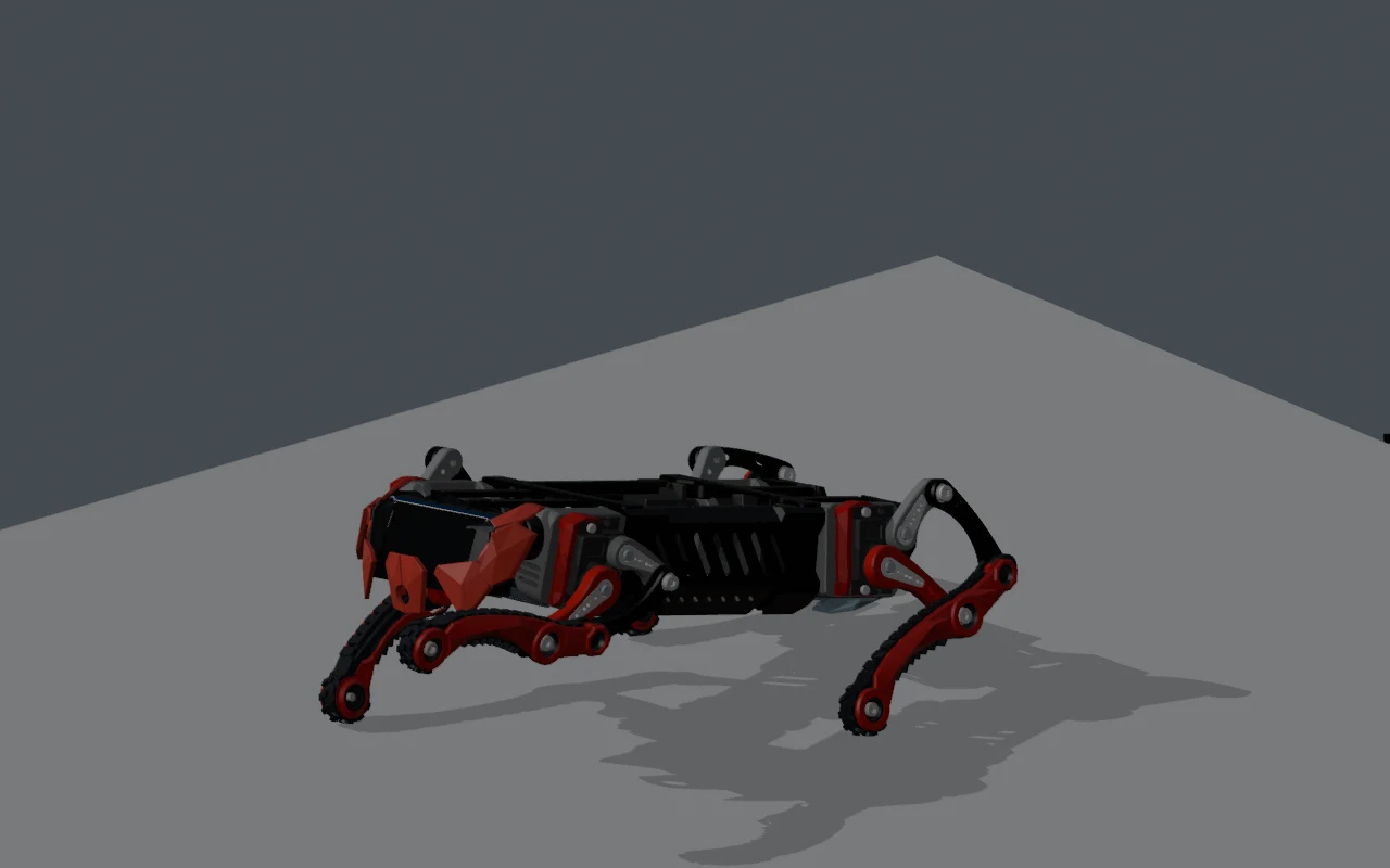
Walk → Run → Walk, excerpted from the September 23 Blender export. 15.3 seconds at 2× playback, without audio. Flight and planted contacts are animation/kinematic results; physical bounding stability is unverified.
Crab now has six ongoing directions: left, right, forward, backward and two
turning directions. The planner enters its wider stance over three seconds,
one foot at a time. Finish holds that stance. Full-stride Crab turning specifies
32.73° per cycle in the model; it is not a measured final heading. V2’s eight
old fixed-angle turn clips were removed from firmware. V1 keeps its existing
fixed turns and finite Crab asset.
The current firmware catalog has 23 finite gestures/postures alongside the
algorithmic gaits. These revisions preserve different intentions rather than
using one lying-down pose for every command.
Motion
Current recording
End behavior
Worm
20 s; two slow deep body waves
Returns to standing
Shrug
14 s; seated, both front arms raised to the sides
Returns to standing
Play Dead
7 s; collapse with front hands about 45.35 mm farther forward than Lay Down
22 s; Sit, reposition front feet, supported push, then vertical chassis over rear lower legs
Experimental held pose; balance, torque and recovery remain unqualified
The full video at the top of this journal was exported before the latest
Worm, Shrug, Play Dead and six-direction Crab revisions. It shows the preceding
choreography and evolving appearance; it is not a visual verification of every
current command. The current range download is taken from the newer sources.
Body Control now exposes channel mapping, direction, model reference angles,
pulse conversion, Home and explicit Save. Saved values belong to the individual
body. Commanded pulse readback is not feedback from a joint-position sensor.
Mapping edits and Save disable outputs; deliberate Home/move actions engage
them. The output controller checks linkage closure and bounds entry transitions.
The latest CONTROLLER_VALIDATION.md records:
Evidence
September 24 result
Current application
0.7.0-p4-compact-motion, 2,369,264 bytes
Flash and boot
Application write verified; boot and gateway authentication confirmed
Stored calibration
Saved mapping retained through the application-only update; outputs disabled afterward
Software checks
29 native/desktop checks and 72 gateway/protocol checks passed; dashboard motion-race checks also passed
Compiled clip geometry
23 clips, 61,919 comparison samples; maximum full-sole vertex difference 0.012861 mm
Those are recorded development results, not checks rerun on the robot for this
website entry. Earlier deployment and offline sections refer to their own
application checkpoints. Previous hardware bench observations used two
unloaded servos with no linkages.
The runtime geometry still identifies the upright 24/38/24/55 mechanism from
September 21. The September 23 scene synchronization and September 24 support
widening are later Blender work. Updating appearance or placement in Blender does
not regenerate controller geometry or qualify the changed body automatically.
The body and battery entry records those
packaging changes and the remaining reconciliation.
Sources: V2 model README.md, motions/gestures/catalog.json, gesture records,
locomotion configuration, the dashboard controls and CONTROLLER_VALIDATION.md
in the local robot checkout after 3f872e7; Blender motion-export and
expressive-motion records. The source manifest
identifies the exact files and hashes used for this entry.
September 28, 2026 — Leverage, motion speed and feedback planning#
This entry reviews the September 25 gait revision and the latest saved
motion-speed implementation, including the current uncommitted controller
validation record. It also records the next step toward responsive gait in
the September 28 integration plan.
Lower working references, unchanged gesture paths#
The continuous gaits were revised to improve linkage leverage while retaining
the established solver. These signed body-reference values belong to the
planner’s geometry; they are not measured chassis-to-floor heights.
Planner quantity
Before revision
Revised value
Walk body reference
−2 mm
−8 mm
Forward Run body reference
−6 mm
−9 mm
Forward Run nose-up bias
6°
3°
Forward Run maximum lift
22 mm
18 mm
Backward Run / turn body reference
−2 mm
−8 mm
Crab body reference
−18 mm
−22 mm
Crawl body reference
−35 mm
−35 mm, retained
Walk retains its 92 mm sweep, 30 mm rearward bias and 14 mm lift. Forward
Run retains its 104 mm maximum sweep. Crab establishes its first anchors over
two cycles, with three for backward movement. Its steady travel, stance width
and cadence are unchanged. Crawl enters from the revised walking-ready pose.
Named Stand and the 23 compiled gestures retain their existing paths; Stand
is distinct from the continuous gait’s working reference.
The recorded offline full-sole check covers 14,391 robot poses, including
speed changes and Finish. Maximum horizontal foot error is 0.000070 mm;
minimum output transmission angle is 46.61° in planned stance and 37.57° in
swing, with at least 3.13 mm extension remaining. These are sampled geometric
results for the controller model. They do not establish torque, traction,
continuous collision clearance or the fit of the subsequently narrowed body.
Any finite positive numeric multiplier; default 2×
What changes
Step planning and cadence; settings can change during walking
Entry and clip clocks use the multiplier when the next named motion starts
Persistence
Existing gait-control behavior
Save on robot stores the multiplier; Read from robot confirms it
Geometry
Revised working references above
Existing motion paths retained
Physical qualification
Loaded gait still unverified
Accepted multipliers are not a measured safe tracking envelope
Saving the named-motion value stops outputs through the existing controller;
starting a subsequent motion resumes operation. The setting has its own
four-byte storage record and does not rewrite joint calibration. A value
above 3× is valid for this control even though advanced gait cadence has a
separate 3× maximum.
Prior 3× value retained and read back after another reboot
Persistence, not high-speed tracking
Production-controller tests exercise all 23 clips at several rates up to 12×.
Those numbers test time scaling; they are not recommended assembled operating
speeds. Higher-rate frame timing, physical shaft tracking and loaded gestures
remain unmeasured. The recorded application SHA-256 is
50a9092e3cde37a7c2644820f6e5082e2b5de29be79cac8f89b556fca0e9eaed.
Next: response to the body, not just changing a command#
Variable stride and speed are implemented. Response to tilt is a separate
feedback problem. The proposed loop is LSM6DS3 samples → attitude estimate →
local P4 gait correction → existing servo output controller. The sensor is
reported received; its driver, installation and active correction loop have
not been verified. Initial targets are 208 Hz acquisition and 50 Hz servo
updates, subject to implementation and physical testing.
ROS 2 can help expose and record this telemetry through a Q6A adapter. The
fast correction loop remains local to the P4 for either build option. See
Wired, Wireless and ROS 2 for the planned
software responsibilities and current implementation stages.
The latest compact Wireless model in Blender uses a different front/rear placement and
rear shoulder-clearance study. Neither moving the legs in Blender nor passing
the older controller-model checks synchronizes or qualifies that assembly.
The mechanical journal records the 82.5 mm
frame, remaining refit work and separate calibration references.
Sources: the captured CONTROLLER_VALIDATION.md, robot commit 270537f and
its integration/budget records, plus the dated Blender reviews. The
source manifest identifies the
September 28 snapshot. These results were read from development records;
no hardware tests were rerun for this website entry.
October 6, 2026 — Physical test, compact linkage and the full motion library#
The chassis has been printed, but it could not stand on its MG90 servos.
LCD and shell pieces remain unprinted. After researching alternatives, Greg
is retaining the MG90s and reducing weight, replacing the heavy battery bank
with separate batteries and onboard charging boards, and revising the legs.
Replacement parts are still printing; this new assembly has not been tested.
The approximately 20% lower weight and 20% greater lifting force are current
owner estimates, not measured loaded results.
The candidate now includes all 23 named motions, with 31,031 source/preview
samples in the Blender motion library. It has not replaced the shared model
or been installed in firmware. The detailed motion entry
records the per-motion changes, including adjusted Sit/Rest landings and
refitted body paths, alongside the preserved timing and choreography.
Point from the complete offline library. Modeled appearance parts remain unprinted; this preview does not show the revised robot lifting itself.
Reduced reach accepted as an experimental fit; input dead center remains
Native candidate tests
Six of seven pass; historical Upright reach assertion fails
The old reach comparison is retained, not weakened to report a clean pass
Combined front-crank travel
243.868° versus 225° in the provisional mapping
A center shift alone cannot fit the span; measure usable shaft travel
Blender/native pose agreement
46 nonsequential poses agree within about 0.000027 mm
Confirms model agreement, not torque, balance or whole-body clearance
Physical revised assembly
Parts still printing
Standing, loaded tracking, clearances and power remain to test
Separately, the committed controller uses a 96 mm full Walk sweep, 8.85 mm
Walk lift and −8 mm body offset. Continuous Crawl has a −22 mm body offset,
18 mm sweep and up to 4 mm lift. The named Crouch gesture retains a −35 mm
terminal body translation; it is a different motion. Automatic movement uses
a common joint-speed limit that can stretch timing without shortening the path.
The IMU estimator is now implemented in source. Sensor acquisition and balance
correction are not connected to it yet. The software entry
also records continuous steering, ROS desktop checks and the hotspot result,
including the failed sustained-session test. The rebuild entry
documents the physical result and structural/power response.
Sources: the October 6 manifest
identifies the reviewed controller files, local research handoffs and Blender
images. Physical observations and improvement estimates are Greg’s October 6
report; the earlier entries above retain their original dates and assumptions.
October 8, 2026 — Standing, walking and command response#
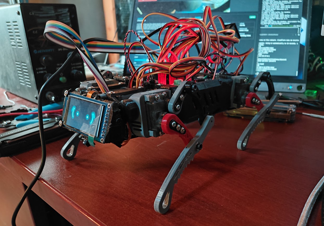
The owner reports that the robot can now stand, walk and respond to commands.
The carapace is not attached and Active Operator has not been tested.
Observation
October 6
October 8
Physical standing
Printed chassis could not stand on MG90 servos
Standing reported
Physical walking
Lighter parts still printing; revised assembly untested
Walking reported
Command response
No new physical result in that rebuild entry
Responding to commands reported
Appearance
LCD and shell pieces unprinted for the failed attempt
LCD lit in current photograph; carapace not attached
Performance measurements
Approximate improvements only
No new mass, lifting-force, speed or endurance measurements supplied
Active Operator
No physical acceptance result
Explicitly untested
Owner photograph of the current exposed assembly. Walking and command response are owner reports; the still image does not establish speed, tracking accuracy or endurance.
This result changes the physical-build status. It does not identify the exact
firmware/model/calibration used, regenerate the September range dataset, or
close every reach, servo-travel and clearance question in the October 6 study.
The new build entry links the latest
mounting-part exports. Face/media work and
responsive commands have their own
source and device evidence. Live IMU balance correction remains integration work.
Source: the owner’s October 8 report and photograph; provenance is recorded in
the October 8 manifest.
Exterior shell printing has begun, the owner reports further weight modifications,
and the power supply is now rated 4 A. The build entry
contains the current Blender design, dated print exports and the power details
still to document. The October 8 walking report remains the physical baseline.
Local Lay Down and Play Dead authoring now lifts and places each foot before
lowering the body. The generator specifies an 8 mm lift, 0.8 seconds per initial
placement, and a two-second lowering segment. Original start/end references and
seven-second authored clip durations are retained.
Offline comparison
Lay Down
Play Dead
Previous peak joint speed
216.36°/s
308.62°/s
Revised peak joint speed
137.59°/s
156.16°/s
Revised minimum modeled body clearance
0.15 mm
0.15 mm
Hardware qualified
No
No
Collision checked
No
No
The local P4 recovery path retraces the completed grounded clip before entering
a new named motion. These are source and sampled-geometry observations, not
measured torque, physical balance or proof of the installed firmware. The
before/after JSON and
source manifest retain the values and
reviewed hashes. All earlier geometry experiments above remain dated history.
Ordinary boot now uses crouch, shoulder alignment and a staged rise rather than full calibration Home. Body Control adds saved self-leveling On/Off, response strength, damping and roll/pitch targets. The firmware journal records installation of 0.8.46 and live readback; loaded physical compensation remains unverified.
The October 13 assembly report supplies 566 g mass and 5 V power. A local geometry calculator compares fixed shaft locations, linkage closure, joint travel and modeled torque demand. The current shorter-link study shows why reduced size can worsen transmission geometry. Read the complete startup, leveling and linkage report.
October 15, 2026 — Revised gaits, Wave and leveling diagnostics#
The October 15 report records longer
commanded Walk/Run/Crawl/Crab strokes, bare-leg contact corrections, PCA9685 pulse
staggering and a 6.2-second seated Wave. Body Control adds a saved level reference,
commanded per-leg feedback and stationary gyro-bias calibration. Wi-Fi installation
is recorded through 0.8.52; loaded movement and electrical benefit remain unverified.
The offline studies retain narrow or negative modeled support margins in some
conditions, including Crab turns and Wave’s seating transition. Passing linkage,
calibration mapping and firmware tests does not resolve those physical questions.
The September showcase above has not been replaced with a claim that it shows
these new paths.
Gait Development Journal: From Eight Servos to Twelve