Building the next Ainekio body#
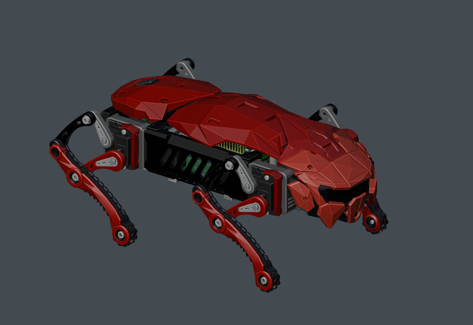
October 12 Blender assembly, neutral stance.
Ainekio is a small four-legged robot. Its working V1 body uses eight servos,
with two motors positioning each leg. V2 adds a third joint per leg, a new
chassis, and an ESP32-P4 controller. The aim is a twelve-servo body that moves
reliably and is easy to service.
The extra joint matters because it moves a foot sideways. V1’s legs primarily
move forward, backward, up, and down. V2 will also be able to change its stance
width and use that movement in poses. The current work adds Freestyle-generated targets to the shared gait solver;
prepared gestures remain available in manual Body Control.
Automatic balance and adaptation to uneven ground require further sensing,
control and physical testing.
October 27 motion follow-up#
A supported stretch verified all nine targets
after calibration positioning. The asymmetric compensation from that trial is
kept separate from the generic training motion. Freestyle now uses complete
programs and actual body events for recovery; loaded performance remains open.
Current hardware: October 26#
The current body record
reports 650 g, twelve feedback-modified Miuzei MG90S servos and a 2S
battery / Mini560 buck / HiLetgo USB-C charger assembly. SHARGE is no longer
used. Pack capacity and running time remain unmeasured. The compact linkage
lengths are 35 / 20 / 28 / 38 / 55 mm for carrier, crank, pickup, rod and lower leg.
The new fixed training stand has three printable parts and a 140 × 110 mm base.
Download its STLs and the one-piece power carrier.
Supported Stand and one finite Walk cycle completed after a firmware stack repair;
loaded chatter and reliable floor walking remain open. Freestyle’s new target
and training work uses shaft
arrival to work toward those results. The October 27 follow-up replaces the
continuation loop with finite programs and event-triggered recovery.
October 21 revision#
New photographs and body-control results
show the reassembled robot, revised red face surround and brighter LCD design.
A ground repair restored useful feedback and a measured Stand-and-hold trial
passed. Installed firmware is recorded through 0.8.113; physical disconnect
behavior and the newer inactivity-rest feature remain to test.
Loaded gait trials and host learning
now connect joint, IMU and camera observations to separate Walk/Run policy
comparisons. Earlier tracking gains are modest; reliable locomotion and metric
camera accuracy remain open. See the October 21 build.
October 18 feedback rebuild#
The feedback-servo rebuild adds
fourth-wire position readings from all twelve servos through a CD74HC4067
multiplexer. Unloaded calibration is complete; measured Stand remains disabled
pending supported tests with the linkages reinstalled. Walking trials still
showed sagging and foot drag. Revised chassis exports include battery, tray,
servo, gyro and display mounts. See the physical rebuild in the gallery.
October 15 motion revision#
Revised motion and leveling controls
cover Walk, Run, Crawl, Crab, a larger seated Wave, staggered servo pulse phases,
a level-reference control and stationary gyro calibration. The journal records
installation through 0.8.52. Commanded leg diagnostics are not measured joint
positions; loaded gait, gesture clearance and leveling performance remain open.
October 14 baseline#
The hardware journal records 566 g, 5 V and MG90 servos for the October 13 assembly. The startup and leveling report covers staged boot posture, saved self-leveling controls and the new local geometry calculator. Firmware 0.8.46 installation and live control readback are recorded; loaded self-leveling remains unverified.
Body Control also gains body-event settings, SD recording, downloads and Wi-Fi maintenance. The full model-selected wake/stretch routine remains incomplete. The existing thumbnail is the October 12 Blender view, not a new assembly photograph.
Shell and power report: October 12#
I have begun printing the shell, made further weight modifications, and
switched to a 4 A power supply. The later October 13 report specifies 5 V;
measured current draw and the final battery configuration still need recording. The new build entry
contains current Blender views, 27 prototype exports and revised grounded-motion
comparisons. Shell fit and Active Operator testing are still pending.
Physical movement baseline: October 8#
The robot can stand, walk and respond to commands. This follows the failed
standing attempt two days earlier.
The carapace is not attached and Active Operator has not been tested. The
physical build update includes the current
photograph and a side-by-side account of the two attempts.
The latest committed exports add LCD-carrier braces, a 20×30 speaker holder,
compact carriers/cranks/pickups, and electronics/power mounting parts. Local
camera-carrier and longer front-tray exports are still being developed. The October 14
firmware record and October 13 mass/voltage report add evidence; a complete
reproducible assembly record remains open. Earlier 20% improvements remain estimates.
The October 6 power decision dropped the heavy 10,000 mAh rechargeable bank in favor of
separate batteries and onboard charging circuit boards. The October 26 entry above records the selected boards and pack arrangement.
Cell capacity and runtime remain unmeasured.
The earlier Anker and SHARGE studies remain dated design iterations.
Wireless, with the Q6A offboard over Wi-Fi, is the current build priority.
Wired retains the onboard-Q6A/native-USB alternative. The October 5–6 offline leg
candidate uses a 35 mm carrier, 20 mm crank, 28 mm pickup, 38 mm rod and
55 mm distal leg. All 23 named motions have been remapped in Blender, with
reduced Upright reach and unresolved servo travel. The installed walking build’s firmware/model revision still needs recording.
| Build record | Latest detail |
|---|
| Standing, walking and mounting exports | Current physical result, photograph and repository part snapshots |
| Face, camera and voice | Working LCD and dated media evidence, plus local expression previews |
| Responsive commands | Task/conversation split, connection controls and Active Operator test boundary |
| Lighter rebuild and new power direction | Standing result, servo decision, material removal, board retainers and the next printed assembly |
| Compact linkage and 23 motions | Geometry comparison, changed gestures, Blender previews and remaining qualification |
| Steering, sensing and connections | Wireless priority, IMU estimator, camera profiles, ROS tools and connection tests |
| V1 versus V2 | Mechanics, dated motion ranges, controllers, Q6A and the two power options |
| Continuing gait journal | Physical result and compact candidate, followed by dated controller records and earlier videos |
| September 28 compact body and face | Earlier frame narrowing, bank packaging, LCD carrier and assembly marks |
| September 24 body and battery study | Earlier red shell, reinforced tabs, width changes and Anker placement experiments |
| Compact legs and horn fit | Earlier geometry alternatives and dated print files |
The P4/gateway source now includes continuous steering and shared joint-speed
control. IMU acquisition and configurable balance correction are now connected.
Loaded correction remains unverified. ROS 2 tools have recorded checks; the robot
adapter and native-USB body transport remain integration work. The October 13
Wi-Fi recovery run passed for 469 seconds; earlier sustained-session failures
remain part of the connection history.
V1 remains supported. V2 stood and walked on October 8.
The
September 15 prototype post contains physical
leg photographs; the V1 hardware guide
records the earlier robot’s parts and wiring.
Changes from V1#
September 7 design comparison. The current comparison is linked above.
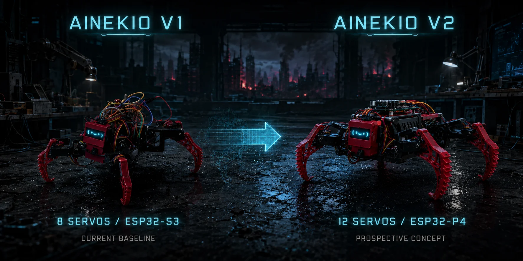
September 7 concept art: V1 is on the left and an earlier V2 concept is on the right.
The leg reference is OpenHarmony Puppy by 杜邦线丶小战士 (pcbguy).
The final geometry will follow leg tests and component measurements.
| Part | Working V1 | Planned V2 |
|---|
| Legs | Two joints per leg; eight MG90S servos | Three joints per leg; twelve MG90S-class servos |
| Foot placement | Forward/backward and up/down | Adds sideways movement at the hip |
| Chassis | Sesame-derived printed body | Ainekio chassis fitted to the new parts |
| Controller | ESP32-S3 N16R8 | ESP32-P4 for body timing, safety, and peripherals |
| Motion | Scripted poses and sequences | Twelve-joint sequences with calibration and smooth transitions |
| Power | Existing 5 V / 5 A servo supply | Supply chosen from measured loads |
MetaHuman OS, the software that handles conversation and decisions, will
continue to request actions such as “stand” or “walk” through the robot’s
network gateway. The controller on the body will turn those requests into
joint movements and enforce their limits.
Legs and chassis#
Earlier design direction, retained for the build history.
The early V2 leg plan had hip roll for sideways movement, hip pitch for
forward and backward movement, and a knee that bends the leg. Together they
provide more foot-placement options and room for body lean and expressive
poses. Speed is not the first priority.
OpenHarmony Puppy V2 provides a reference for lightweight MG90S legs, supported
pivots, and linkages that keep motor weight close to the body. Local files
include printable STL models and STEP assemblies converted for Blender.
Testing will establish how those ideas fit Ainekio’s shorter, broader shape.
The chassis is being assembled in Blender around the leg mounts, board models,
connectors, and front camera/display carrier. The original OpenHarmony-derived
assembly has since been revised through the
direct-rod and compact-leg work.
The September 9 short-rod study
remains a separate historical comparison of alternatives.
Cables need clearance throughout a leg’s movement. Programming, charging, power
connections, legs, and electronics should remain accessible for replacement
and repair without dismantling the whole body.
Printed leg development: September 12–14#
The new prototype photographs
show a printed leg assembled in partly folded, folded, and extended poses.
The records now include a failed shell fit and horn measurements from actual
hardware, as well as saved Blender changes. Many refinements apply to one
front-left leg or a separate review file; they are not all combined into one
released four-leg print set.
| Part or interface | Recorded revision | What still needs checking |
|---|
| Part_009 input arm and Part_024 link | A 21 mm input arm was paired with an imported approximately 24.64 mm link, 4 mm thick, then matched to four legs | Full moving-part clearance and recalibration; earlier 40 mm shared-link and 27 mm trials remain separate iterations |
| Part_020 / Part_022 shells over Part_027 | A failed print fit led to 0.30 mm mating allowance and a 0.15 mm entrance chamfer in the FL clearance review | Reprinted fit and the thinner local collar rims |
| Horn arm pockets in Part_009 / Part_023 | Physical arms measured 2 mm; pockets revised to 2.1 mm while reference horn meshes remain 1.75 mm | Actual seating and the separate Part_008 sleeve interface |
| Part_023 cavity | Later uniform 2.1 mm floor and flush outer ledge; inner seat retained | Printed seating and loaded behavior |
| Part_027 lower-leg neck | Nominal 8 mm neck and enlarged end, retaining 5 mm thickness and mounting bores | Physical strength and joint travel |
| Part_025 screw collar | Separate 1.5 mm-high collar, retaining its bore and mating faces | A longer screw than the modeled M3×6 reference is required |
| Slim foot options | 9.2 mm assembled width; flat, chevron, then lugged tread with Ø7 × 1.5 mm bolt pockets | The slim variants retain about 0.10 mm cavity allowance, distinct from the earlier 0.30 mm fit revision; print fit and traction remain open |
The shoulder-motion work is still an unfinished chassis-clearance study.
Its 270° swivel-servo brief does not establish usable assembled travel: the
recorded draft has pose-dependent interference and awaits final review.
The latest build log shows the source images
and explains the alternatives and their remaining limitations.
Parts in the September 10 Blender assembly#
This is the earlier electronics/body snapshot. The leg refinements above are
newer; inclusion here does not make a reference board or display a final choice.
These quantities describe models in the assembly or the stated servo plan.
They are not a purchase checklist. Dimensions below are in millimeters; board
dimensions exclude connectors unless stated. Mounting patterns are distances
between hole centers. The electronics import notes and front-face design record
identify the following references.
| Component | Quantity | Board size; mounting pattern | How it is used and what remains open |
|---|
| Radxa Dragon Q6A v1.21 | 1 model | 85 × 56 × 1.6; four Ø3.5 holes, 58 × 49 pattern | Computer model at the front, ports facing the end panel. Its Blender placement does not establish an installed OS or onboard MetaHuman runtime. |
| ESP32-P4-WIFI6 | 1 model | Supplied STEP measures about 71.07 × 21.02 × 1.60 | Body controller candidate at the rear. Exact board wiring and the twelve-servo firmware port remain open. |
| Adafruit PCA9685 servo driver, product 815 | 1 model | 62.23 × 25.4 × 1.57; four Ø2.5 holes, 55.88 × 19.05 pattern | Separate servo-pulse board modeled beside the P4. Final driver selection and wiring are not proven by placement. |
| MG90S-class joint servos | 12 planned | Three joints per leg | The new body still needs loaded leg tests and calibration; supplier-specific dimensions and torque must be checked against the actual motors. |
| Waveshare 2inch LCD Module | 1 reference model | 58 × 35 × 1.6; four Ø2 holes, 53 × 30 pattern | Landscape face display, including four M2×6 spacers in the official model. Final display product remains undecided. |
| OV5647 camera, Arducam B0033 dimensional reference | 1 reference model | 25 × 24; four Ø2 holes, 21 × 12.5 pattern | Above the display. Thickness, lens depth, rear connector, and minor components are approximate envelopes. |
| Top and bottom covers | 2 Blender parts | Each 112 wide, 3 base thickness, eight Ø3 mounting holes | WIP 13 closed unused openings. Bottom tabs remain. Printed seating and strength are untested. |
| Removable front carrier | 1 Blender part | Adds 3 to the two front cover screw stacks; four 4-high camera standoffs | LCD and camera share the carrier. Screw lengths, retention, and cables still need actual hardware. |
The P4 model came from the supplied ESP32-P4-WIFI6_3d-20260109.stp file.
Its four polygonal mounting openings measure about 1.66 mm across the inscribed
circle, on a 54.164 × 18.25 mm pattern. These are model measurements, not a
manufacturer drilling specification.
The Q6A and PCA9685 models came from Radxa’s hardware downloads
and Adafruit’s CAD files.
The display uses the Waveshare module reference
and its mechanical drawing.
The camera board dimensions come from the Arducam B0033 drawing.
How the Blender assembly was built#
The revision names below refer to saved Complete-WIP Blender files. Their
order documents the modeling work, not a completed physical assembly procedure.
| Revision | Construction change | Retained features or unfinished work |
|---|
| WIP 1 | Arrange four leg assemblies around the body | Establishes a layout, not balanced motion. |
| WIP 2 | Fit center mounts and front/rear end panels | Check mount interfaces before adding electronics. |
| WIP 3–4 | Import Q6A, PCA9685, then P4 STEP models at millimeter scale | Include connector overhangs and underside components. |
| WIP 5 | Widen the chassis 40 mm, 20 each side, and place the three boards | Preserve screw and bearing features; Q6A at front, P4 and PCA9685 toward rear. |
| WIP 6–8 | Round the servo housings, try oval then vertical openings, synchronize the manually edited housing across all four legs | WIP 8 supersedes the earlier opening patterns. |
| WIP 9–10 | Add 3 mm center bow to Part_026, then replace the concentrated bend with continuous arcs | Preserve bearing seats, pivot holes, 4 mm thickness, approximately 5.015 mm waist, and 2.2 mm slots. |
| WIP 11 | Cut two USB-stack openings and an Ethernet opening in the front panel | No extra nominal port allowance; Q6A tray lip trimming remains. |
| WIP 12 | Widen top and bottom covers from 72 to 112 mm and align their eight frame holes | Preserve 3 mm base thickness; frame still has a 0.2 mm mounting-height step. |
| WIP 13 | Close 18 unused top openings and 15 unused bottom openings | Each cover retains only eight Ø3 frame holes and the existing outer contour. |
| WIP 14 | Mount a camera above a landscape LCD on a removable front carrier | Reuse front cover screw axes; hardware selection, cabling, optics, and electrical compatibility remain open. |
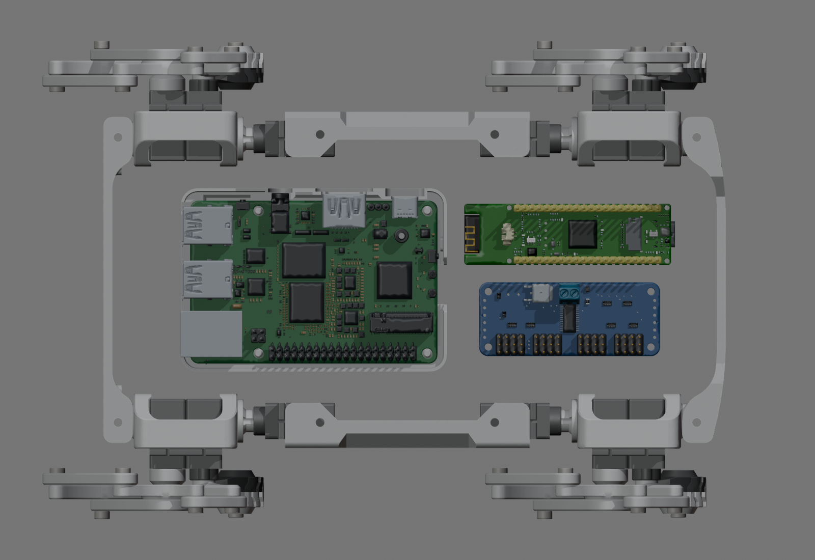
WIP 5 board placement, before the later covers and face. This records that
revision’s layout; it is not a wiring diagram.
Robot Layout → LeftRightSpacing_mm controls the leg roots, center mounts,
inserted panel sections, covers, and later face mounting positions. At the
97 mm setting, the covers are 112 mm wide. Widening moves the existing mounting
features rather than scaling their holes. The cover and face checks also
exercised the 107 mm setting.
The WIP 5 layout provides a 6 mm gap behind the Q6A tray and between the rear
board envelopes. Four tray cutouts include 0.3 mm around modeled connectors.
Those clearances belong to that saved layout. Real plugs, cable bends, cooling,
and full leg motion need a separate check; the tray still overlaps the later
panel and bottom cover and requires trimming.
Choices and alternatives#
| Decision | Earlier option | September 10 evidence |
|---|
| Servo pulses | Direct P4 outputs favored; external PWM optional | A PCA9685 board is now modeled. The electrical choice and firmware integration remain unverified. |
| Onboard computer | Required onboard Linux computing outside the initial plan | A Q6A is now included in the packaging study. This is a mechanical change; no deployed software role is established here. |
| Knee linkage | OpenHarmony-derived printed links | Three fixed-servo short-rod mechanisms were also studied. The supported relay is a research candidate; none passed the complete brief. |
| Cover openings | Broad access cutouts in WIP 12 | WIP 13 keeps only the frame screw holes; cooling still needs investigation. |
| Face hardware | Camera and display not yet packaged | WIP 14 uses Waveshare LCD and OV5647 references on a removable carrier. Final modules are not selected. |
Exact fastener counts and lengths, bearing/shaft procurement, filament and print
settings, V2 audio hardware, battery, regulator, harness, and assembly torque
are not settled in the reviewed records. This page will need those measured
details before it can serve as a complete replication guide.
Controller and motion: earlier plan and September progress#
The paragraphs below preserve the earlier controller plan. By September 17,
the project had a separate twelve-joint model and thirty geometric motions,
and the selected signal driver was a HUAREW PCA9685 breakout. That hardware
selection is distinct from the Adafruit board model in the September 10 Blender
table. The integration record
reports a built motion image, pending flash and unavailable physical motion.
ESP32-S3 and ESP32-P4 name different controller chip families. Choosing the P4
does not make the existing firmware ready for the new body. Board pins,
communication hardware, camera, and audio still need their own implementation
and tests; V1’s S3 wiring map is not a P4 wiring guide.
The original plan favored twelve servo-control signals generated directly by
the P4. The later Blender model includes a PCA9685 pulse-width modulation (PWM) board.
Both approaches still require pin allocation, control software, calibration,
and peripheral tests; a board model is not evidence that either path is wired.
A scripted motion consists of frames. Each frame specifies a target angle for
each joint and how long the transition should take. For V2, a frame will contain
twelve targets. Interpolation supplies the positions between frames so the
robot moves smoothly instead of jumping from one pose to the next.
Planned controls include center calibration, direction inversion, minimum and
maximum angles, velocity and acceleration limits, safe rest poses, and staged
startup and stand-up sequences. Existing movements can first be adapted with
the four new lateral joints held neutral, then use those joints selectively.
Walk, stop, stand, sit, bow, and wave remain examples of higher-level requests.
At the initial planning stage, the body core, motion assets, protocol validators,
and MetaHuman motion-plan schema described eight joints. They needed to agree on the new joint
names, limits, and advertised capabilities before accepting twelve-joint plans.
Power: measure the load before choosing the supply#
Earlier electrical planning, retained for context. The October 6 direction
uses separate batteries and onboard charging boards. The bank option below
is historical; the final cells, boards and power arrangement are unspecified.
The owner reports V1 operating on its existing 5 V / 5 A supply. The design note
proposes measuring that robot first, then evaluating a 5–6 A supply line, or
rail, under V2 loads. Four extra servos mean the V1 result cannot establish the
new robot’s requirements.
Controller and servo power will branch near the supply. Motor current will
bypass the P4 board, while a common ground gives the controller and servos the
same electrical reference. A bulk capacitor near the servo rail can help with
brief current demands; the supply still has to sustain the load. Smooth
acceleration and staged movement will be part of testing.
A battery or power bank must deliver the needed current at 5 V continuously,
cope with startup and motion peaks, and remain stable in voltage and
temperature. An advertised USB-PD wattage does not by itself establish those
properties. The final power source remains undecided.
Build and test sequence#
- Make one leg. Measure fit, servo horn alignment, travel, interference,
stiffness, bearing support, printed weight, and reachable foot positions.
The horn is the arm on the servo shaft; backlash is unwanted joint play.
Both affect how accurately a printed assembly follows a commanded angle.
- Measure V1 power use and adjust the leg design. Use the existing robot
and the experimental leg to inform the mechanical and electrical choices.
- Test the P4 in stages. Check signals and calibration, then one loaded
leg, two legs, and all twelve servos.
- Validate the modeled chassis and design the wiring harness. Check them
against measured parts and power needs, with room for motion and service access.
- Port scripted movements. Tune transitions before the final complete print.
- Repeat normal movements under load. Test standing, sitting, walking,
turning, and stopping. Watch for binding, supply shutdown, brownouts
(voltage drops that reset electronics), and frequent near-stall operation.
Check controller capacity and repair access as well.
Later options#
The initial plan deferred IMU stabilization and real-time inverse kinematics.
The current V2 controller now implements both, including configurable local
leveling; successful loaded correction still needs physical validation. Adaptive
terrain response, foot-contact sensing and learned locomotion remain later work.
Higher-cost servos and wireless charging were outside the initial build plan.
Onboard Linux computing was also excluded from that first scope. The Q6A model
records the September 10 wide-body packaging study; its board and tray were
retired from the September 17 narrow chassis. No onboard Q6A runtime is
established by either Blender layout.
The MetaHuman redesign can develop against V1
while these mechanics are tested. Current project status
tracks the latest summary. This page’s September 10 mechanical details come
from the electronics import notes and the WIP 5, 10–14 design and saved-file
reports. Their checks cover saved geometry and static fit; no new physical test
was performed for this documentation update.