V2 · 12 servosDated experiment
A Lighter Rebuild After the Standing Test
The printed chassis could not stand on its MG90 servos. The next iteration keeps those servos, removes weight, replaces the battery bank and revises the legs.
Published 4 min read
October 8: The lighter robot stands, walks, and responds to commands.
What the printed chassis taught me
I have printed the chassis, but not the LCD or shell pieces. In that configuration, the robot could not stand up on its MG90 servos. That result has driven most of this week’s design work.
After researching alternative servos, I have decided to keep the MG90s for now and change the robot around them. I am removing material from components in Blender, replacing the heavy 10,000 mAh rechargeable battery bank, and shortening the leg carrier to improve the lifting arrangement. The new parts are still printing; I have not tested this revised assembly yet.
My current estimate is roughly 20% lighter, with approximately 20% more lifting force. Those are estimates for the developing revision, not measured results from a successful standing test. The cutouts aim to retain structural integrity; the new prints still need to demonstrate that under load.
What changes between the two attempts
| Build decision | Previous attempt / plan | Current direction |
|---|---|---|
| Physical result | Printed chassis could not stand on its MG90 servos | Replacement parts printing; standing test pending |
| Servos | MG90 | Keep MG90 after researching alternatives |
| Structure | Heavier chassis components | Cutouts and local material removal in Blender, while retaining the needed mounting and load-bearing regions |
| Power | Integrated 10,000 mAh rechargeable battery bank | Separate batteries and onboard charging circuit boards; more complex, but adjustable and more versatile |
| Legs | Longer carrier in the preceding linkage | Shorter carrier and revised linkage for greater lifting capability and quicker motion |
| LCD and shell | Modeled appearance | Still unprinted; not part of the reported physical standing result |
The new battery arrangement is a design decision, not a finished electrical specification. Cell type, capacity, charging-board models, the final power path and measured runtime are not established in this update. The earlier Anker and SHARGE bank studies remain useful design history, but no longer describe the selected power approach.
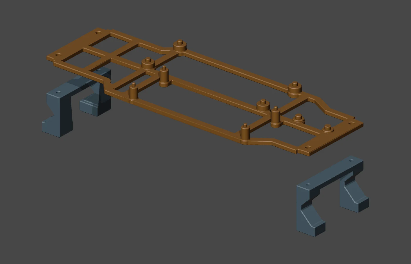
Removing material where the interfaces can stay
One documented example is the October 1 front bearing panel. Its Blender mesh volume changed from about 5,421 to 4,347 mm³, a 19.81% material reduction for that part. That number is separate from my approximate overall weight estimate above.
The revised panel retains its 78.5 mm overall width and bearing/mounting axes. It uses a 2.5 mm main web and four oval openings. The 12.5 mm bearing pockets and approximately 4.5 mm pocket depth remain. The modeling checks establish those interfaces and sampled clearances; they do not establish printed strength.
Other changes simplify assembly as well as the shape:
| Component | Earlier arrangement | Latest recorded Blender revision |
|---|---|---|
| Side supports and trays | Separate parts with an extra joint | One solid per side; redundant joint holes and shelves removed |
| Side attachment | Four separate connectors | Direct fastening through existing bottom-slot tabs |
| Rear tray | Tray plus two inside connectors | One printable solid, retaining the frame and rear-panel mounting axes |
| Front and rear panels | Less bracing to the center crossbars | Removable braces with flat print faces and retained panel interfaces |
| Electronics bridge | Board locating features | Seven removable retainers with modeled screw access |
Not every intermediate reinforcement was kept. The October 2 deep bosses and outward mounting pads were subsequently removed. The latest center-support record restores the original outlines and uses 1.5 mm through-pilots in the existing shelves, aligned to 2.1 mm crossbar clearances. The earlier deep-boss revision should not be treated as the current print instruction.
Keeping the electronics serviceable
The October 3 bridge has three P4 edge clips, two clips for the purple board and two spacer retainers for the Adafruit board. Its modeled fasteners are seven M2 screws with 6 mm under-head length, 4 mm heads and 2 mm head height. The record calls for fitting the boards on the removed bridge because the crossbars restrict screwdriver access once installed.
The eight bridge/retainer meshes passed the recorded closed-mesh, local-fit and 432 fastener-probe checks. Actual screw grip, printed fit and strength remain untested. The purple board reference is also approximate.
The appearance is still being developed in Blender
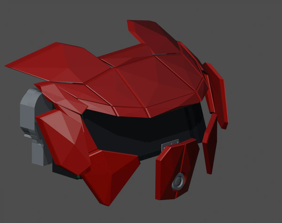
The face has also changed. The September 28 afternoon study fitted an imported 23-panel angular mask around the rectangular display, with an 18° display tilt and a forward-facing camera. Later work refined side keys, printed retaining pins and the panel braces. A temple-fastener experiment was reverted, so it is not part of the current mounting claim.
The next useful result is a repeat standing test with the lighter parts and revised legs. Weights for both configurations, the actual batteries and boards installed, and any flexing or failed interfaces will make that comparison much more useful than another render alone.
Record behind this entry
The physical result, servo decision, battery change, approximate improvements
and current printing status come from my October 6 build report. Dimensions
and assembly revisions come from the dated Blender review records:
front-panel-mask-fit-review.md, side-tray-joint-review.md,
rear-tray-joint-review.md, electronics-bridge-fit-review.md and
mask-side-mount-fit-review.md.
The source and image manifest records the reviewed revisions. All illustrations in this entry are Blender images, not photographs of the printed assembly.
A Lighter Rebuild After the Standing Test
https://ainek.io/posts/2026-10-06-lighter-rebuild/