V2 · 12 servosDated experiment
Compact Wireless Body: Battery Clearance, Face and Assembly
Independent Wired and Wireless Blender designs, an 82.5 mm Wireless frame, revised front-leg placement, rear carrier relief, a fitted LCD carrier and assembly reference marks.
Published 7 min read
Making room for two build options
Later development — October 6: the printed chassis could not stand on its MG90 servos. The lighter rebuild keeps those servos and replaces the heavy battery bank with separate batteries and onboard charging boards. New parts are printing. The dimensions and bank packaging below preserve the September 28 iteration.
The mechanical work since September 24 covers the frame, electronics tray, battery, face and assembly references. The build is now split into Wired, which carries the Q6A computer, and Wireless, which leaves it offboard. The integration entry compares their transport, ROS 2 and power plans.
The latest Wireless record reaches 82.5 mm across the outside of the frame. It restores the original front carriers, moves the front leg assemblies 4.1 mm forward, and retains relief cuts in the rear carriers. The tray, support length, end panels and shell still need to follow that new placement. This is an in-progress fit revision, not a finished print set.
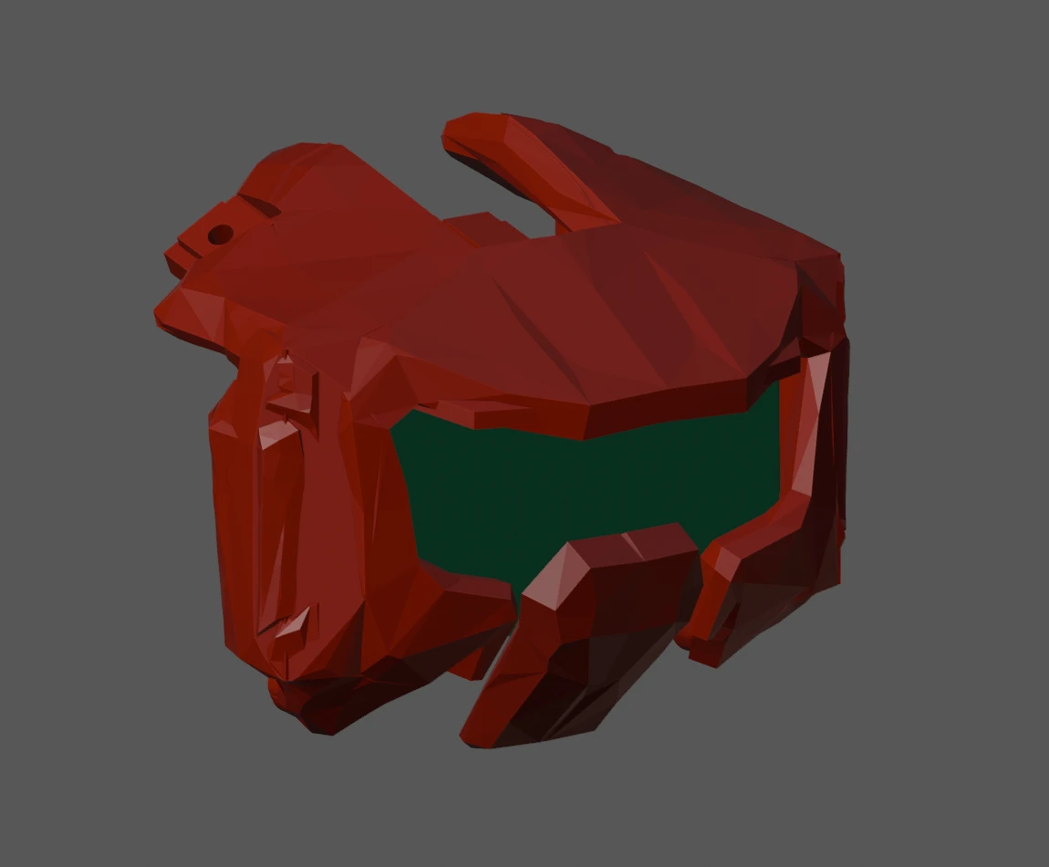
Separate designs in Blender
The former modeling scene became Wireless, with Wired made as an independent copy. Their objects, mesh data and materials can now be edited separately. Parent relationships, constraints and driver references were retargeted within each design. The existing Gait and Motions scenes were preserved, and save/reopen checks verified the split.
Both designs started from the same hardware layout. Subsequent compact edits apply to Wireless; they do not automatically change the animation scenes or the Wired body. The older Blender showcase therefore remains useful motion history, but does not show today’s frame clearances.
Width, battery and leg placement
The battery reference has changed from the earlier Anker envelope to the 115 × 51 × 26 mm SHARGE Pouch. The bank stays centered laterally with its port facing rearward. The table keeps the successive frame dimensions tied to their own revisions.
| Geometry decision | Wider baseline / intermediate revision | Latest Wireless record |
|---|---|---|
| Outer frame width | 100.3 mm restored baseline; then 94.3 mm compact Wireless layout | 82.5 mm |
| Front-to-rear pivot spacing | 147.7 mm in the 94.3 mm layout | 151.8 mm after moving the front assemblies 4.1 mm forward |
| Front Part_003 carriers | An intermediate trial relieved all four carriers | Original front geometry restored, including mounting holes, rails and surface details |
| Rear Part_003 carriers | Original outline constrained narrowing around the bank | Battery relief retained |
| Checked inward shoulder movement | 0–17° in the 94.3 mm layout at fixed carrier/crank pose | Front 0–17°; rear 0–13.4°, at the reviewed carrier/crank poses |
| Electronics tray and bridge | Included in the 94.3 mm layout’s fit checks | Excluded from the final narrowing decision; refit outstanding |
| Panels and shell | Earlier placements and geometry | Support length, end-panel and shell fitting still to follow |
Moving the front assemblies forward recovered clearance for the original front carriers without continuing to cut them down. Their sampled minimum battery gap is approximately 0.590 mm at 17° inward swing, with a conservative bound above 0.56 mm between 0.1° samples. At the rear, the limiting moving hardware is Part_006 at approximately 0.523 mm over the checked 0–13.4° range.
The fixed Part_002 servo bodies still nominally touch the battery sides. Those near-zero clearances do not provide a practical manufacturing allowance. The bank, boards and fixed hardware kept their dimensions; no servo casing was trimmed to make the fit work.
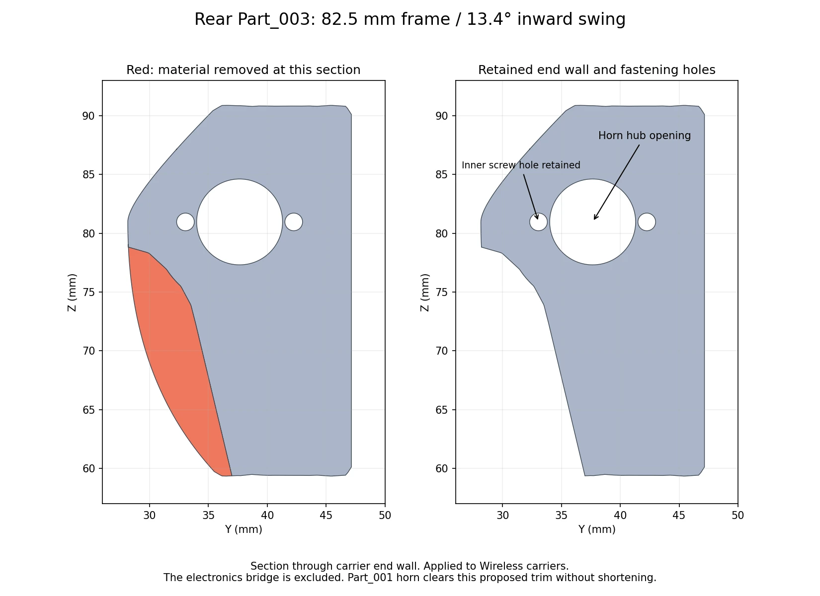
These are battery-clearance checks at particular carrier/crank poses. They neither establish a complete gait envelope nor change firmware limits. The most recent review preserves the rear assemblies, unrelated geometry and all 71 animation actions. It does not prove loaded strength, printed fit or unrestricted motion of the narrower body.
The onboard electronics tray
Before the split, the Q6A tray was reduced from roughly 189.42 × 81 mm to 173.92 × 61 mm. It retains a 1.2 mm floor, rounded ventilation slots and supports for the P4 and servo driver. Small ledges carry the underside of the Q6A Armor case while leaving its fins exposed.
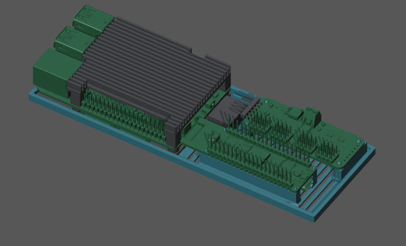
The tray’s modeled material volume fell from 20.28 to 12.96 cm³, a 36.1% reduction. That is a geometric comparison, not a measured print mass or strength result. The case remains an approximate reference with about 0.3 mm modeled side clearance. A later rear-panel wrap follows the tray with a nominal 0.2 mm gap; full-motion checks were not repeated for that panel edit.
The intermediate 94.3 mm Wireless design instead placed the P4 and Adafruit servo driver side by side over the bank, with the purple IMU reference at the bottom/front and its headers facing outward. A separate bridge locates on tray pegs. Positive retention and cable fit remain physical prototype work, and the subsequent 82.5 mm narrowing requires that bridge to be refitted.
Display, carrier and front panel
The face now uses a 62 × 29 mm PCB reference for the XIITIA 1.9-inch display. This imported reference was reconstructed from product information and images; hole and component details are estimated rather than supplied by the manufacturer. The front mask was widened locally around it, retaining the angular exterior, and the chin became a separate object.
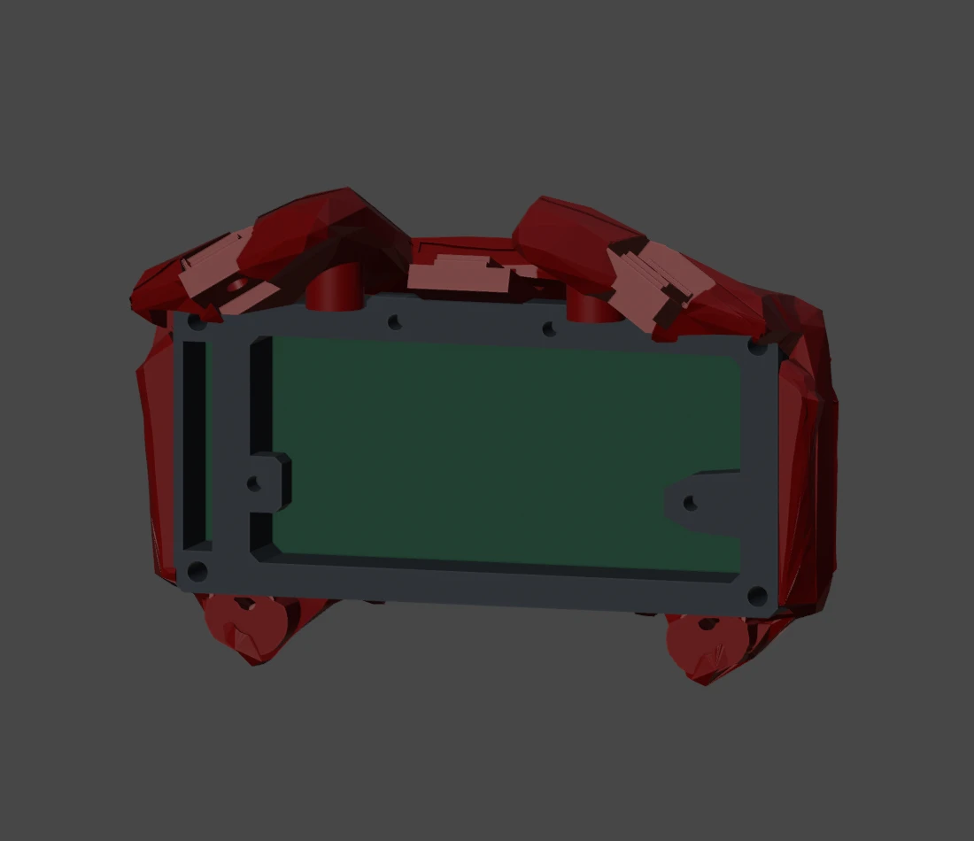
| Interface | September 27 fit | September 28 Wireless change |
|---|---|---|
| Carrier back | Flat rear plane; 7.3374 mm maximum seating depth | Face assembly moved 1.5 mm forward; four matching 1.5 mm spacers retain mounting alignment |
| LCD-to-mask mounting | Modeled 58 × 25 mm pattern; 2.1 mm carrier clearance holes aligned to mask pilots | Pattern retained; actual board and screw fit still need checking |
| Header passage | 3.04 × 20.82 mm opening with a 3 mm reinforcing web above and below | Approximately 0.337 mm axial gap to the front bearing-support face in that review’s placement |
| Camera ribbon | Separate lower passage | Preview transition adjusted to follow the moved camera |
| Fasteners | Separate PCB-to-mask and carrier-to-panel patterns | Screw-head seats and screw lengths remain deferred |
The header measurement covers the modeled bare pins, not an installed plug or wire bend. It was made before the latest front-leg relocation, so it is not a clearance certificate for the complete 82.5 mm assembly. Some side protector contacts also remain. This is why front-panel and shell refitting stay on the next-work list.
Assembly marks and calibration references
The leg assembly work added 12 pairs of alignment marks across four legs: carrier to end panel, main arm to carrier, and crank to main arm. The modeled grooves are 0.6 mm wide and 0.3 mm deep.
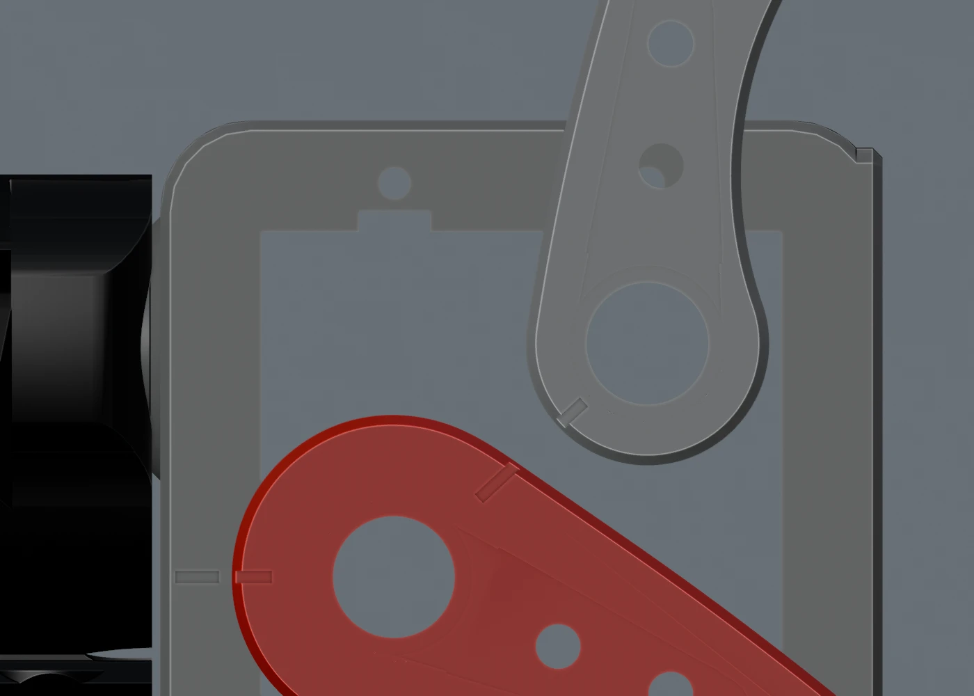
The newer reported pulse endpoints are 300–3000 µs. Their arithmetic midpoint is 1650 µs, but measured shaft travel and a matching assembled neutral remain unresolved. The marks must not be reinterpreted as a new 1650 µs installation reference merely because that number is the midpoint. The review did not change firmware calibration or qualify all four legs.
What is ready to use from this entry?
The images and dimensions above document saved modeling work through 13:04 PDT on September 28. The latest scene split, face fit and Wireless carrier changes were saved and independently reopened in their review records. They did not create a new complete STL/GLB release. Earlier dated print downloads remain available as earlier revisions.
The next mechanical work is to fit the supports, panels, electronics bridge and shell to the latest front/rear positions, resolve practical battery and connector allowances, and check the resulting assembly through its required motions before recording printed and loaded results.
The source and image manifest identifies the reviewed files and their hashes. Download the captured Wireless clearance note for the exact scope of the final front/rear study. For controls and feedback, continue to the gait journal.
Compact Wireless Body: Battery Clearance, Face and Assembly
https://ainek.io/posts/2026-09-28-compact-body/