V2 · 12 servosDated experiment
Refining the body and fitting the Anker battery
A red shell, revised mask mounts, reinforced printed tabs and an 80 mm chassis placement: fitting a removable 10,000 mAh Anker bank beneath Ainekio V2.
Published 7 min read
Fitting the body around the parts I have
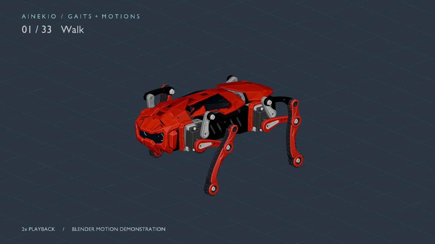
Cover: a frame from the September 23 Blender motion export. The red mask, carapace and exposed linkage are CAD geometry. The subsequent battery and 80 mm modeling changes are separate from this animation snapshot.
Most of the recent design work has been in the body itself: how the mask attaches, how the end plates fit around the bearings, how printed mounts survive assembly, and where the battery can sit while the legs move. The current battery is an Anker PowerCore Slim, 10,000 mAh, chosen because it is already on hand. The underside is being redesigned around a removable bank rather than treating battery packaging as something to solve after the shell is finished.
The eight-versus-twelve-servo comparison brings the mechanics, processing and power arrangements together. The gait journal records the new controls and September 24 firmware deployment.
What has changed in the body
The latest modeling scene measures 80.0 mm between the exterior walls of the center supports, increased from 75 mm. Each support and its leg mechanisms moved 2.5 mm outward. Shoulder-center spacing changed from 56 to 61 mm; that is a different measurement from exterior wall width. The parts were translated, not scaled.
This is still an assembly revision: the spanning front/rear plates retain their 75 mm layout, and the gait and motion scenes retain the previous layout. Their bearing alignment and the revised assembly’s clearances need reconciliation. The earlier 51.2 mm chassis in the September 21 article remains a dated design iteration, not today’s chassis specification.
| Area | September 22–24 change | Remaining work |
|---|---|---|
| Face and mask | Shorter front plate, concealed upper mask receivers and inclined lower screw passages | Actual screw length, print fit and tool access |
| Rear panel | Matching upper/lower corner tapers; about 44 mm at the flat edges, 63.2 mm around the bearings | Reconcile the plate with the wider support placement |
| Center-support tabs | Flared roots and smaller screw pilots after four printed tabs reportedly snapped or split during assembly | Reprint, screw fit and layer strength |
| Electronics | Compared the existing flat fore/aft boards with centered stacked and upright alternatives | Choose and mount the layout with real plugs and cable bends |
| Underside | Fit the rounded Anker bank beneath the moving assemblies | Holder, lower structure and clearance across the complete motion set |
Mask attachment and the printed assembly
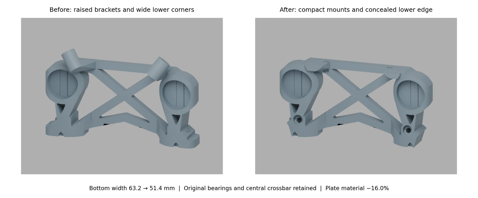
September 23 CAD review. The revised plate uses the LCD-facing surface as its print-bed face. These images show the bracket revision before the later 80 mm support placement.
The raised upper brackets and lower locating pins were replaced by screw mounts. Upper screws pass through 2.2 mm clearance holes into 1.6 mm blind mask pilots. The lower passages incline about 19.8° to clear the LCD and retain material in the cheeks. M2×10 upper and M2×14 lower screws are provisional; the lower tip allowance is only about 0.2 mm in CAD. The separate helmet-to-mask wing attachments still need their own fasteners.
The lower plate corners were subsequently tapered from 63.2 to 51.4 mm at the bottom so they sit inside the mask silhouette. The existing mask/carrier contact and manufacturing-export cleanup remain recorded; this is not a released, fully checked print set.
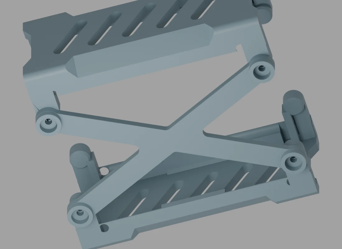
September 23 CAD revision following reported tab failures in printed parts. The temporary brace remains an iteration to reconsider around the battery.
All four original lower tabs reportedly snapped or split along print layers when assembled with linkage fasteners. The revised support uses the smaller screws that worked in Part_003: 1.5 mm pilots, 4 mm deep, with rounded, flared roots. The brace has 2.2 mm clearance holes and 5.4 mm × 2.2 mm head recesses, leaving 2 mm below each head seat. These dimensions describe the revision; they do not establish a measured strength improvement.
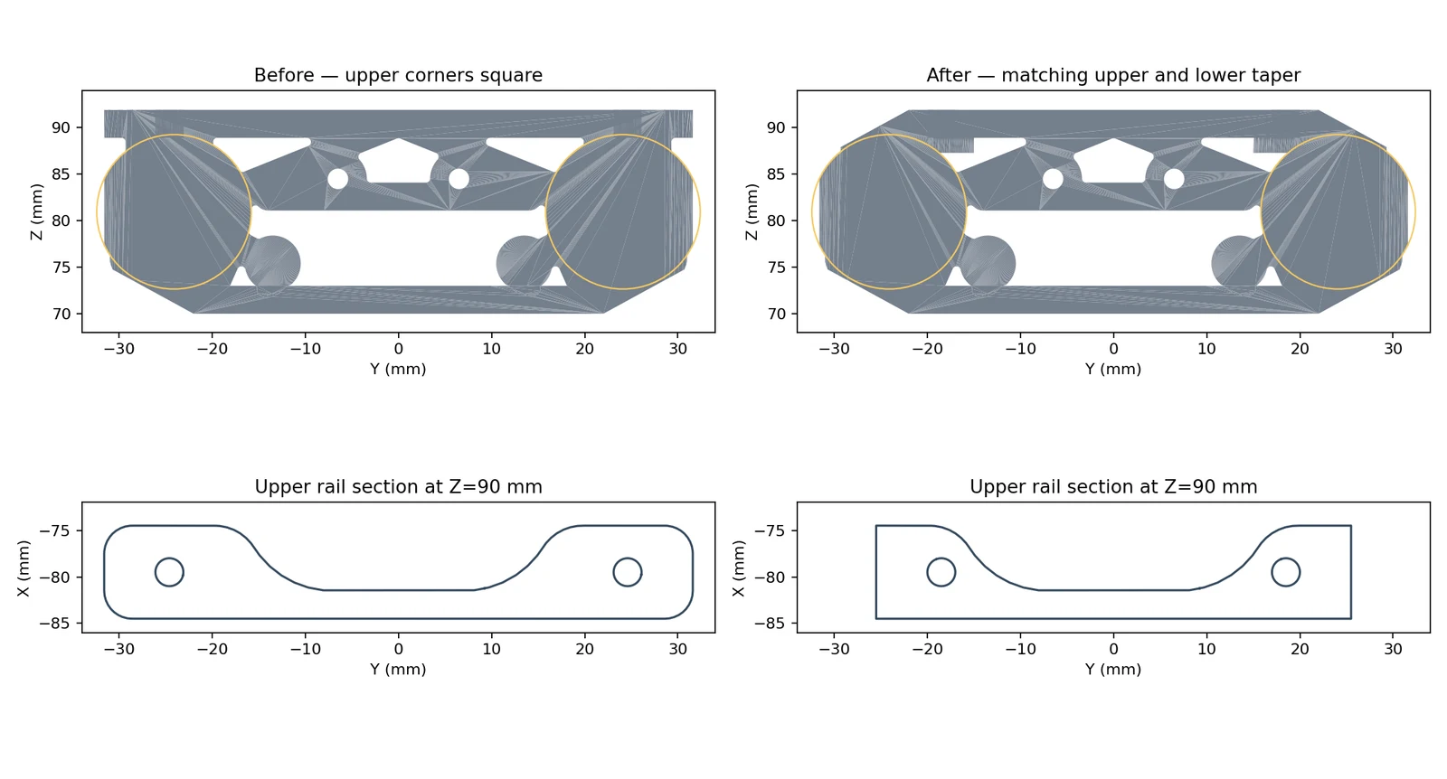
September 23 rear-panel iteration. Bearing support width is retained while the outer corners taper; the later support widening still needs matching plate alignment.
Making space for electronics
The September 23 review compared two centered alternatives to the existing flat fore/aft arrangement. Standing the boards on edge saves about 10 mm of height relative to the proposed horizontal stack. At the then-current 75 mm layout, an 8 mm channel between component envelopes was identified as a starting point for connector trials. The live boards remained flat; the upright arrangement is a study, not installed hardware.
The CAD uses an Adafruit PCA9685 reference model. The selected physical driver is a HUAREW PCA9685 board; the reference mesh does not establish its delivered connector positions or dimensions. Mounts must follow the actual board.
Battery and charging arrangement
Greg’s September 24 update identifies the intended power arrangement:
| Original V1 | Current V2 design | |
|---|---|---|
| Battery | 1,000 mAh LiPo; earlier hardware record gives 2S, 7.4 V | Anker PowerCore Slim, 10,000 mAh |
| Conversion | External buck converter | Bank output; no separate buck converter |
| Charging | External battery charger | Charging integrated into the removable bank |
| Future charging work | No new change reported | Plug-in Qi charging add-on planned |
| Measured robot runtime | Not measured | Not measured |
The exact Anker model suffix, rated watt-hours and output-current label have not been recorded here. The fit mesh is 155 × 72 × 16 mm; these are the owner’s modeling dimensions, not a manufacturer specification inferred from the product name. Qi charging is a future addition, not a demonstrated feature.
Three different fit checkpoints
The fit report contains successive experiments. Their results apply to different battery positions and included parts, so they must be read separately.
| Checkpoint | Battery position in CAD | What was checked |
|---|---|---|
| Earlier 75 mm / Z54 baseline | Upper face Z54 mm; center Z46 mm | 15,627 integer-frame poses across 25 sequences, plus 690 critical quarter-frame samples; no rounded-bank mesh intersections in that scope |
| Virtual 75/80 mm comparison | Highest sampled placement retaining 0.5 mm clearance | Selected tight poses; exclusions listed below; no complete motion sweep at the higher positions |
| Latest 17° front-left placement | Upper face Z56.79191 mm; center Z48.79191 mm | Nominal housing contact at one pose with a 0.0100 mm numerical gap; not an operating clearance |
The earlier all-frame study covered locomotion, including historical turn recordings. It did not qualify seated, lying-down or other non-locomotion gestures with the battery. Its minimum estimated ground clearance was 31.29 mm in walking/variable gait, 16.07 mm in walk–run–walk, 20.00 mm in Crab, and only 2.29 mm in Crawl. A holder beneath the bank would consume some of that space. Those figures cannot be transferred to the latest higher placement.
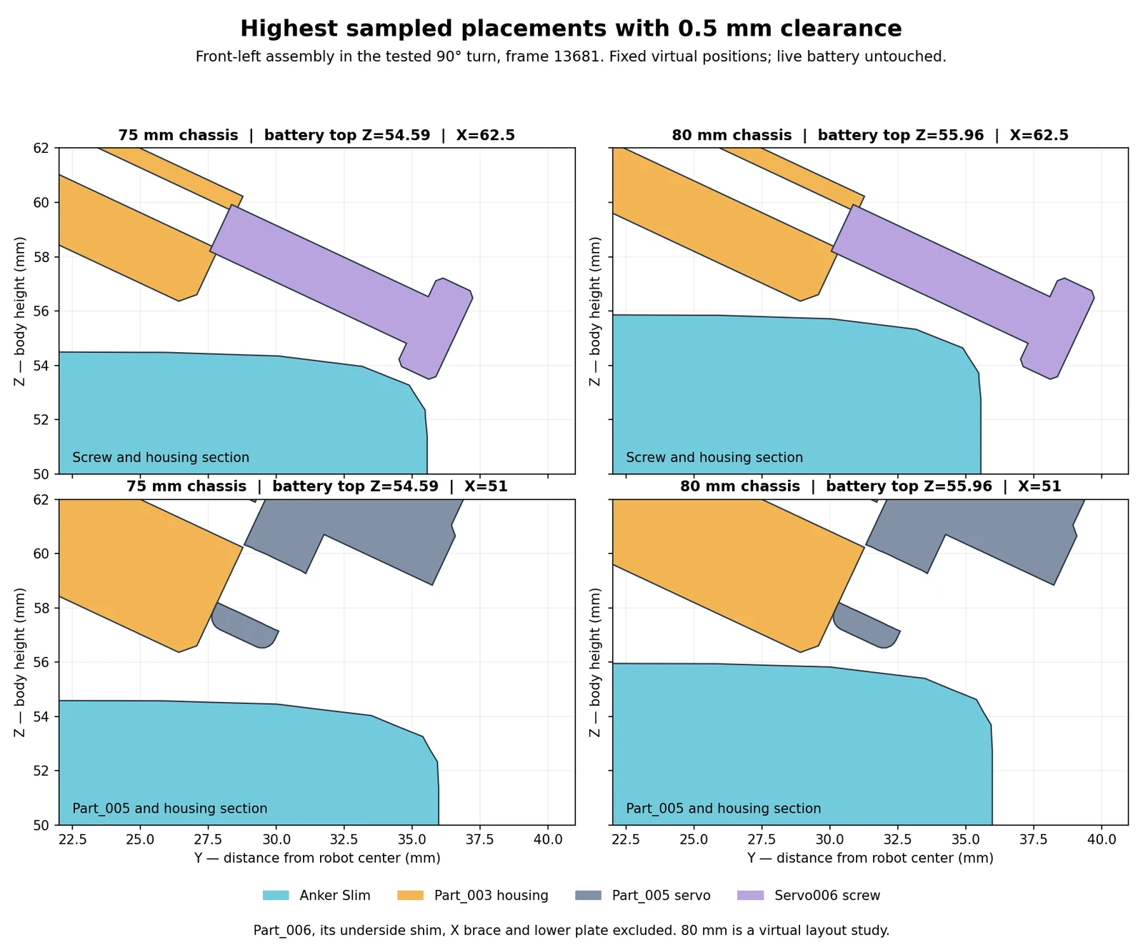
September 24 virtual study, before the modeling scene was widened. Cyan is the battery, orange the housing, purple a screw reference and gray a servo. The plot’s “80 mm virtual” label describes that experiment, not the later saved modeling state.
| Virtual packaging result | 75 mm support-wall width | 80 mm support-wall width |
|---|---|---|
| Nominal inner-wall width | 69 mm | 74 mm |
| Highest sampled battery top with 0.5 mm gap | Z54.590 mm | Z55.956 mm |
| Gap below center-mount undersides at that position | 4.122 mm | 2.755 mm |
| Limiting remaining reference | Servo006 mounting screw | Part_003 housing edge |
This comparison excluded Part_006, its underside shim, the temporary X brace and lower cover, while retaining the Servo006 screw references. Those exclusions make it a packaging experiment, not proof that the complete mechanism and battery fit together. In particular, a servo reference cannot simply disappear from a twelve-servo build. The current underside redesign must resolve the occupied hardware and replacement structure.
The latest one-pose adjustment lowered the bank 0.5005 mm to remove housing overlap at front-left shoulder h=17°, carrier=0°, crank=0°. It is centered between the outer support walls at Y=±40 mm. The report’s opening “75 mm” label predates the saved widening; the separate width record identifies the modeling scene as 80 mm. The single-pose result and its exclusions remain the appropriate scope for that placement.
Next entry in this experiment
The next useful result is a holder and underside arrangement reconciled with the wider supports, followed by clearance checks for the actual latest geometry through gaits, seated poses and floor-level gestures. The electrical comparison needs the bank’s label, measured load and a timed run. Neither the CAD results nor the capacity label supplies battery life.
Source record
This entry uses the September 24 local workspace, including work after robot
repository commit 3f872e7. The main records are chassis-width-review.md,
anker-battery-fit-review.md, front-panel-mask-fit-review.md,
rear-panel-shape-review.md, center-mount-tab-reinforcement-review.md and
electronics-placement-review.md in the Blender workspace. Current width is
taken from the dedicated width record; older review headings retain their
checkpoint dimensions.
Download the source and media manifest for relative source paths, snapshot hashes and image provenance. Earlier leg print files remain dated exports; no new STL release is implied by this update.
Refining the body and fitting the Anker battery
https://ainek.io/posts/2026-09-24-body-and-battery/