V2 · 12 servosDated experiment
Developing the Shell Around the Mechanism
Ainekio's evolving face, collar, roof and fins, with actual CAD views and a record of accepted and rejected design iterations.
Published 4 min read
The body takes shape around the moving parts
Modeling the chassis and redesigning the legs have occupied most of the recent build time. Alongside those mechanical changes, the outer body has been worked through repeated front, side and three-quarter comparisons: the face opening, collar, roof, fins, guards and chin all affect how the robot fits together and how it looks.
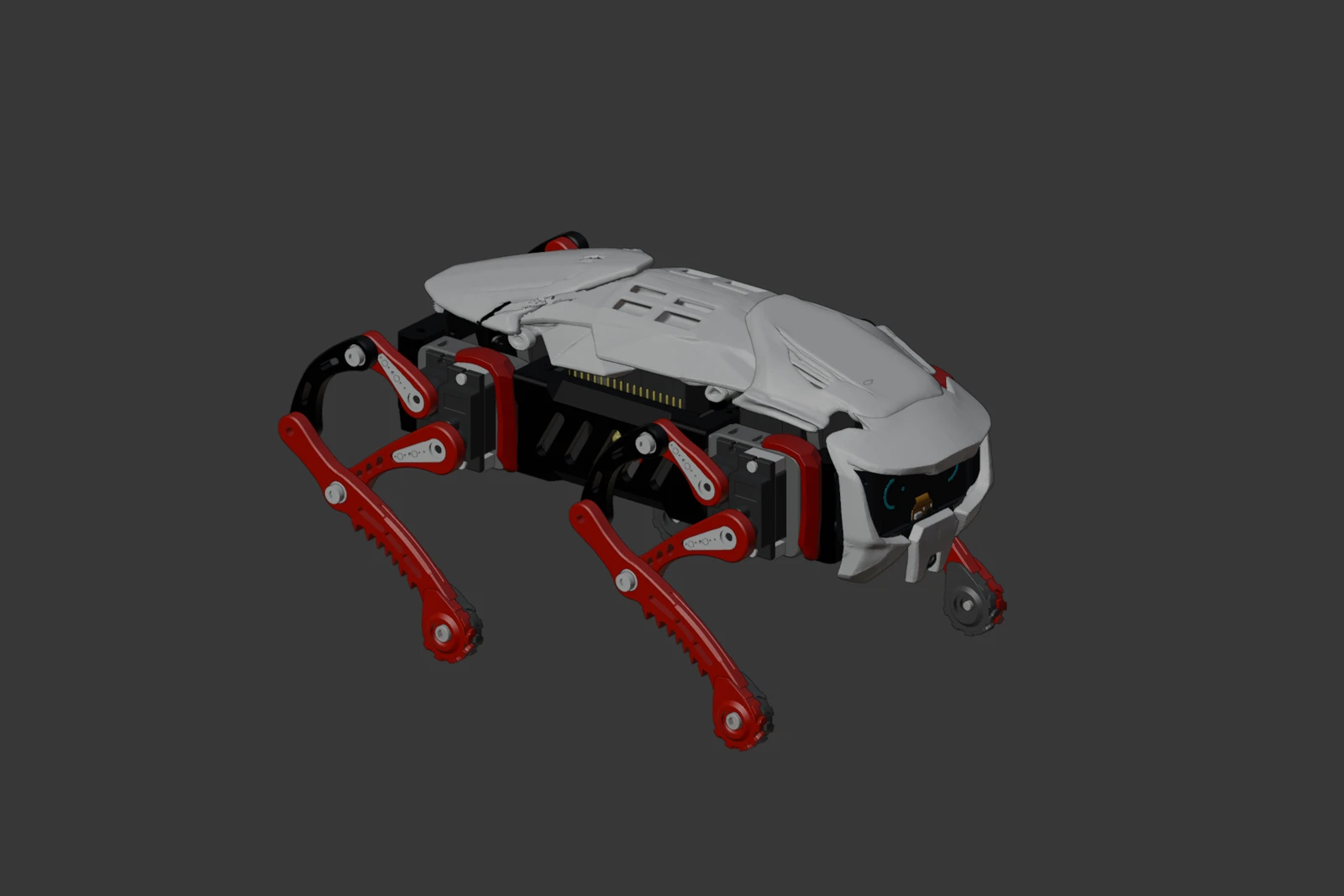
September 20 Blender assembly: shell surfaces around the mechanism.
This post follows the shell revisions. The companion chassis packaging update covers the narrower frame and camera-cable opening, while the compact-leg update records link lengths, print faces and the horn-fit correction.
Comparing the silhouette from more than one direction
The September 19 iteration log records changes against the supplied concept images and imported reference model. A shape that improved one view did not always work in another. Several early shoulder-fin trials were rejected: raising and flattening the old plates did not produce the intended swept profile in both front and side views, and one outline trial folded faces. Those trials were restored instead of being counted as finished geometry.
The retained iterations include a narrower collar with a rounded rear relief, new fin surfaces and supports, localized roof-tip corrections, shallow panel seams and small changes to the brow, cheeks and chin. “Retained” describes that point in the design sequence; the later assembly continued to evolve.
| Area | Problem explored | Recorded response |
|---|---|---|
| Collar | Broad solid center obscured the layered profile | Narrowed shoulders, recessed front edge and enlarged a rounded rear opening |
| Shoulder fins | Earlier plate trials failed the front/side comparison | Rejected those trials; developed new surfaces with prototype supports |
| Roof tips | Unequal outward flare | Matched the outer tips and lowered their outer edges locally |
| Brow and cheeks | Harsh faceted highlights and missing panel divisions | Local crown and shading changes; shallow seams while retaining the face opening |
| Chin | Upper center needed a small convex ridge | Up to 0.6 mm local advance; retained lower geometry and camera opening |
One small roof change, shown before and after
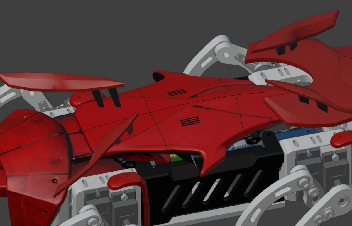
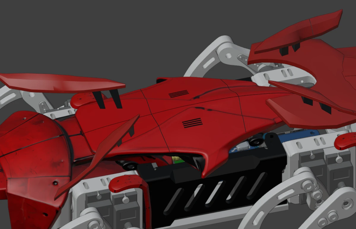
The change is at the pointed outer roof edges, especially the near tip below the vent grooves. Their lateral positions were brought to ±41 mm, from approximately −42.747 and +44.645 mm, and the outermost edges lowered 1 mm. The center roof, vents and fin mounting regions stayed fixed in that pass. These red-shell images document an earlier stage than the pale September 20 assembly shown above.
Rebuilding surfaces and adding attachment geometry
Later on September 19, the neck plate was rebuilt as a simpler symmetric surface with approximately 2 mm paired-surface spacing. Its recorded base mesh changed from 11,099 vertices to 162, and the evaluated shell check found one closed component. This is a result for that plate revision, not a blanket printability result for the robot.
The evening roof sequence explored a hollow interior and vents, then reduced excessive lower-wall depth. A further reference comparison led to a controlled faceted reconstruction, approximately 99 × 41 mm per side, with a mostly level rim, localized 4.4 mm flange step, vent openings, three interior hex mounting pads per side and nominal 1.6 mm walls. The record reports closed evaluated geometry for that pass, with no STL exports from it.
Those successive changes should be read as design history. Their dimensions do not automatically describe every surface in the later assembly or prove that fasteners and print tolerances have been settled.
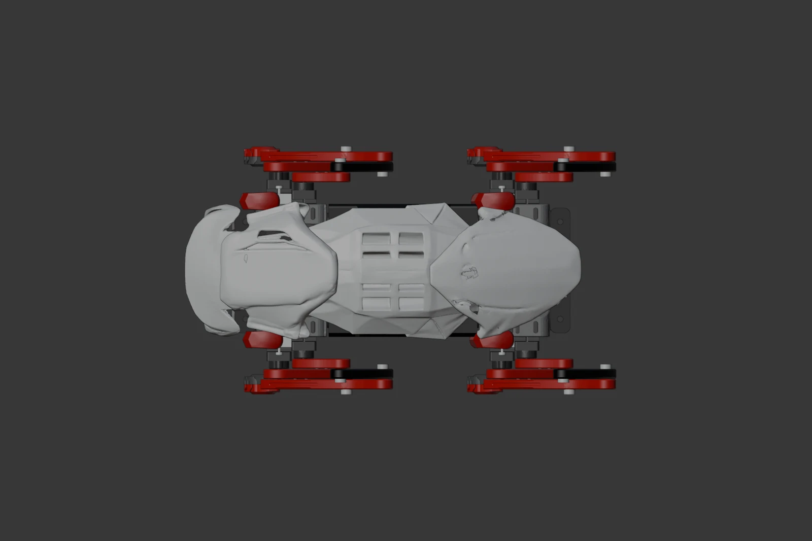
September 20 top view. Together with the side and three-quarter views, this records the assembly’s appearance at that stage. Later saved edits exist; these images retain their capture date rather than claiming to show every subsequent change.
Next: connect the shell decisions to assembly checks
The useful next questions are about the chosen shell and leg combination: where each panel attaches, whether screws remain accessible, how the camera cable bends, and whether the links and servo housings clear the body through the intended motion. Surface cleanup and a closed mesh help prepare a part, but fit, print strength and moving clearance need their own checks.
The gait journal continues the movement experiments. The earlier prototype photographs remain the physical record of the printed legs; they do not show this later shell. The site’s dystopian illustrations remain concept artwork, while the figures in this update document the actual CAD work.
Source record
The September 19 carapace iteration log preserves the accepted, provisional and rejected steps, including the evening neck and roof rebuilds. Its original geometry checks were reviewed for this post, not rerun. Image provenance and source checksums identify the files used here.
Developing the Shell Around the Mechanism
https://ainek.io/posts/2026-09-21-shell-design/