V2 · 12 servosDated experiment
September 15: From CAD to Printed Leg Prototypes
Printed leg prototypes with expressive movement, revised linkage geometry, horn pockets sized from real hardware, and fit lessons for the next iteration.
Published 7 min read
Building the leg, then checking the fit
The last few days have concentrated on the part of Ainekio that has to carry the body: the leg assembly. The work now includes 3D-printed prototypes assembled with servos, linkages, and fasteners, alongside continued Blender revisions. These September 14 photos show a leg in three configurations.
The movement itself has been a highlight of working with the printed assemblies:
The printed prototypes have much more expressive movement than the models I have seen online.
Greg’s observation from the physical prototypes, September 15.
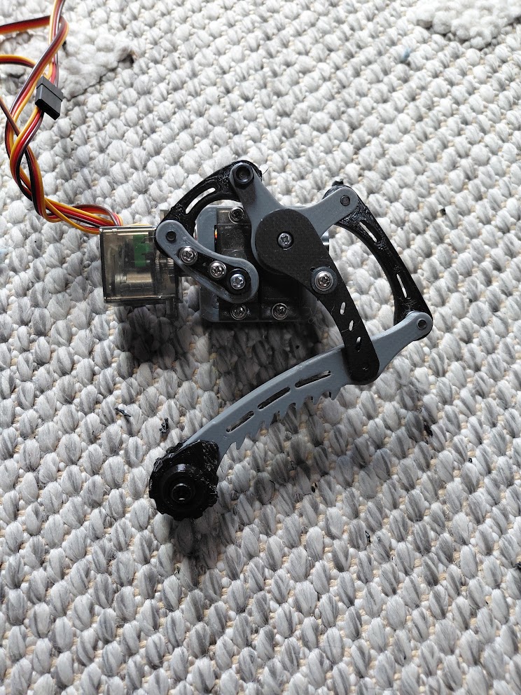
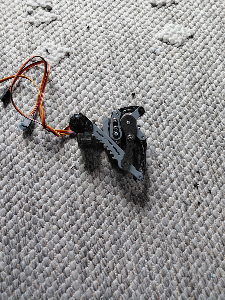
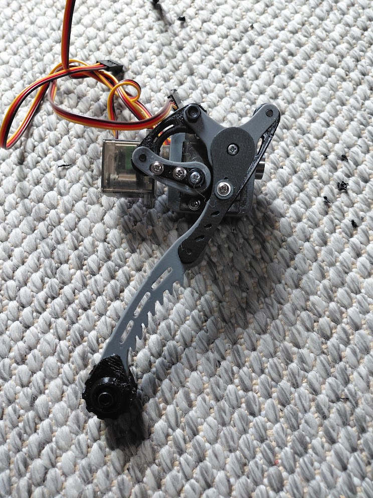
Original prototype photographs; select a photo to inspect it at full size.
The photographs establish that parts have been printed and assembled. They do not measure powered travel, torque, backlash, or the ability to support the complete robot. Later September 14 foot revisions described below have their own CAD records and are not established as printed by these photos.
Finding a linkage that fits around the servos
The September 12–13 linkage work explored several lengths while retaining the servo axes and the surrounding assembly. That matters because lengthening a link can solve one clearance problem while changing how far the leg moves for a given servo angle.
One review used the same 40 mm, 4 mm-thick link at both Part_024 and Part_026, with Part_025’s two arms made equal at 20 mm and Part_009 shortened to 21 mm. This reduced the number of different link shapes, but a modeled bolt near the second servo still limited movement. It was a layout option, not a finished motion solution.
A later review fitted an imported Part_024 at its existing approximately 24.64 mm pivot spacing and 4 mm thickness. Part_009 remained 21 mm. The imported link was positioned and turned over so the bearings seated from the correct side and its curve cleared the housing in the reviewed pose. That mechanical layout was then matched across all four legs. A subsequent review reversed the four Part_024 links end-for-end while preserving their pivots and mesh shapes.
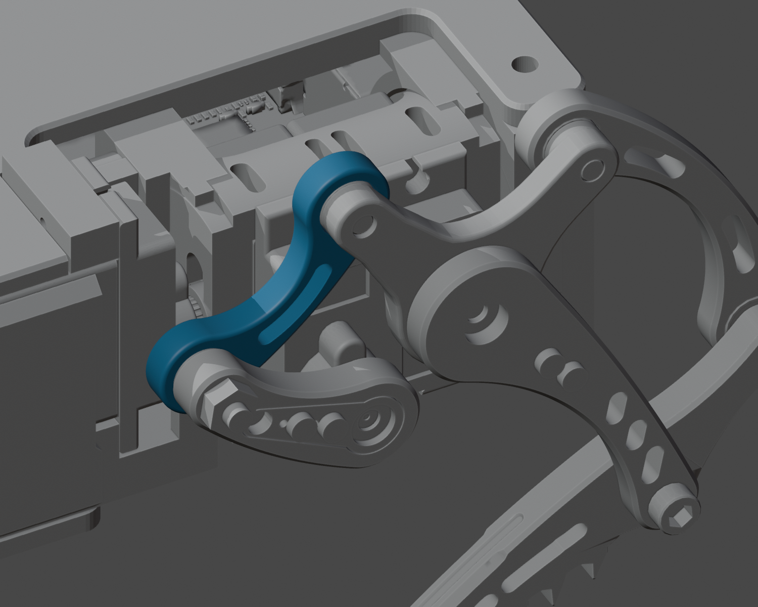
September 13 imported-linkage fit, before the subsequent reversal and local horn, shell, and foot refinements. Blender, September 13.
These revisions change the relationship between servo rotation and leg angle. Earlier gait calibration cannot simply be assumed to apply. The separate September 9 short-rod study remains a record of another research path; its motion ranges do not describe these printed prototypes.
A print that would not fit over the leg
The shell-clearance record documents a concrete assembly problem: printed Part_020 and Part_022 would not fit over Part_027 at the entrance. The captured CAD gaps were approximately 0.106 mm and 0.150 mm on the two sides.
The September 14 clearance revision opened both cavities to 0.30 mm per mating surface and added a 0.15 mm entrance chamfer, giving approximately 0.45 mm at the opening. The cut follows the complete insertion outline of Part_027, including the central teardrop key, rather than one section through the part. The cavity floors, 5 mm clamping stack, screw seats, exterior tread, and lower leg itself were retained.
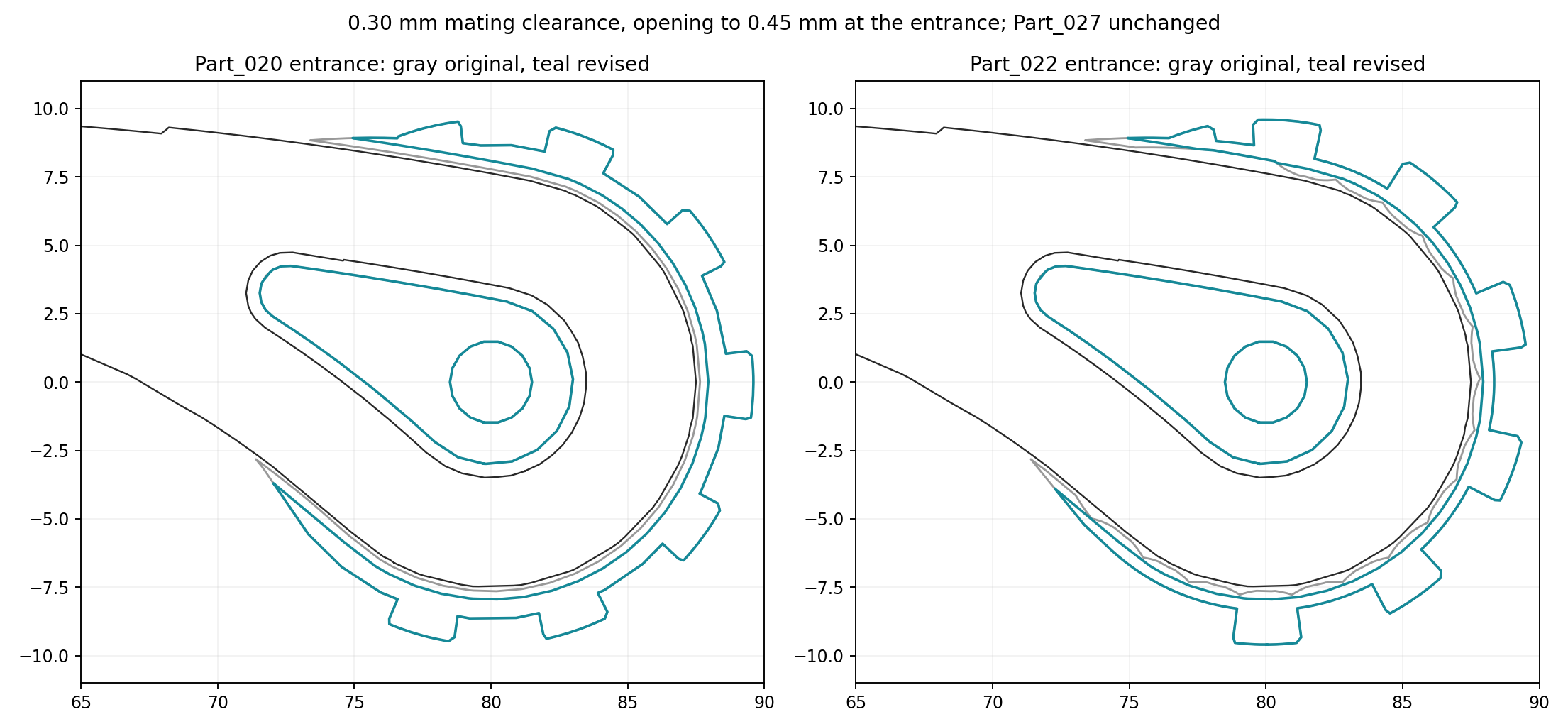
Recorded CAD comparison for the clearance revision. The dimensions describe the model; a new print is needed to establish the resulting fit.
This was a front-left pair in a separate review file. It should not be read as a change already applied to every leg or to every later foot design. The larger cavity also reduces material around the collar: the recorded lip walls are about 0.57 mm and 0.40 mm on the two shells. The thicker backing remains, but that local rim needs attention during the next fit test.
Measuring the horn instead of trusting its model
The horn-recess record reports physical horn arms measured at 2 mm thick, while the reference meshes were still 1.75 mm. That difference explains why a pocket matching the model could be too shallow for the part in hand.
The revised arm pockets in Part_009 and Part_023 are 2.1 mm deep, allowing 0.1 mm nominal depth clearance for the measured arm. Their recorded backing thicknesses are 2.8 mm and 1.9 mm respectively. The straight tapered horn-arm outlines replace an earlier wider shoulder and curved transition that had been rejected.
Part_023 then received a more uniform floor and a flush outer ledge while retaining its inner seat. The final saved check measures the 2.1 mm cavity depth across the pocket and ledge. The central hole remains 2.5 mm, with support retained underneath the inner seat. These are housing changes; the separate Part_008 sleeve fit is still its own problem.
Other local changes improve the fastening and lower-leg geometry. Part_027’s neck was widened to a nominal 8 mm, keeping its 5 mm thickness and pivot bores. Part_025’s outward screw boss became a separate 1.5 mm-high collar. The modeled M3×6 screw ends roughly 0.6 mm below that collar, so the record calls for a longer screw. Splitting the collar does not by itself settle the fastener length or joint strength.
Three iterations of the foot
Later on September 14, the foot shells were developed through a separate slim pair, chevron tread, and deeper lugged tread. Their 9.2 mm assembled width replaces an earlier approximately 15 mm width. Part_027 remains unchanged in this foot sequence.
| Foot revision | Recorded geometry | Next physical check |
|---|---|---|
| Slim symmetric pair | Flat outer faces; 2 mm backing; 0.10 mm nominal cavity allowance | Whether the tight cavity fits this print and material |
| Chevron tread | Same 9.2 mm width; 1 mm-deep grooves at 35°; 0.5 mm perimeter bevel | Printed corners, fit, traction, and durability |
| Lugged tread with bolt recesses | 2.2 mm-deep tread gaps; 1.3 mm center channel; Ø7 × 1.5 mm bolt pockets | Pocket bridging, bolt seating, rim strength, and traction |
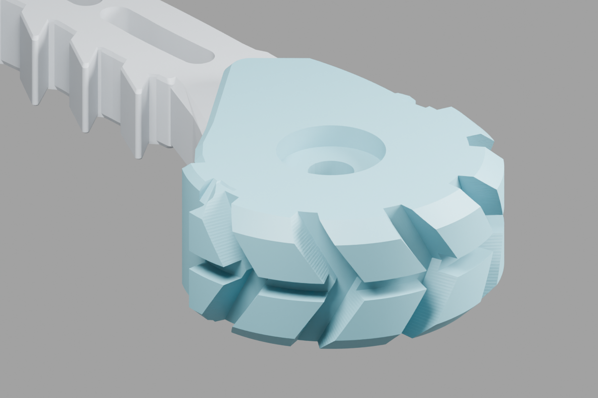
Later foot CAD: the bolt pockets are present in the final saved file. The earlier preview labeled “Bolt Seat Pending” predates those recesses.
The lugged version increases the tread-tip radius to 11 mm, compared with 9.8 mm in the chevron version. The bolt pocket leaves a minimum 0.5 mm floor at its outer rim, with thicker support toward the center. The exports place the flat outside faces on the print bed, with the cavities upward; the bolt pocket therefore introduces a small roof around the shaft opening.
The slim-foot sequence retains its own approximately 0.10 mm cavity allowance. It does not automatically inherit the earlier 0.30 mm shell-fit revision. Comparing those two clearances against real prints is part of choosing the next foot, not evidence that either value is universally correct.
Shoulder motion is still being worked out
The shoulder study investigates a larger swivel envelope while preserving the shaft axis and allowing the leg to bend. Its brief uses a 270° swivel servo, but usable assembled travel depends on the leg pose, chassis, and neighboring legs. That hardware range is not a measured whole-assembly range.
The reviewed folder contains motion probes and draft chassis geometry. Its static report still records clashes involving the proposed socket, servo, and other parked legs, and no final extended-chassis reopening/export result was present. This remains work in progress rather than a completed shoulder fix.
What the next prototype needs to establish
The immediate work is to choose a coherent leg and foot revision, check its printed fit, settle the sleeve and fastening stack, and measure joint travel through bending and swivel. Load-bearing strength, repeatability, cable clearance, and powered behavior then need to be checked on the assembled hardware. A complete V2 walking test is still a separate milestone.
This update uses the September 12–14 linkage, shell-clearance, horn-recess, Part_023, shoulder-motion, and foot revision records reviewed on September 15, plus the three supplied prototype photographs and Greg’s observation about their expressive movement. The dimensional values above belong to those named revisions. Saved CAD/STL checks were read, not rerun; unrecorded print settings, material choices, fastener quantities, and test results have not been filled in.
The V2 build guide connects these leg changes to the body and electronics. The September 10 assembly update preserves the earlier chassis, covers, and camera/display work.
September 15: From CAD to Printed Leg Prototypes
https://ainek.io/posts/2026-09-15-leg-prototypes/