From a leg design to a robot assembly#
Most of the last two days’ Ainekio work has been in Blender. The V2 design now
has four leg assemblies arranged around a body, a wider electronics bay, and
models of the boards that need to fit inside it. Work has also continued on
the leg housings, linkage curves, front connector panel, fitted body covers, and a removable camera/display face.
These are CAD models and geometry checks. V1 remains the working physical
robot; the twelve-servo V2 still needs printed parts, assembly, wiring, and
motion tests. The images in this post are renders of the design files. The
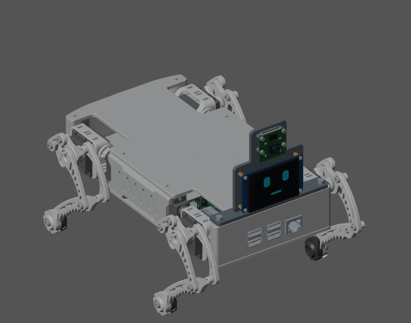
cover image shows the WIP 14 camera/display assembly saved at 18:45 PDT. Its
face graphic is a visual preview, not running display software. Blue covers in
the earlier images are render coloring, not a material selection.
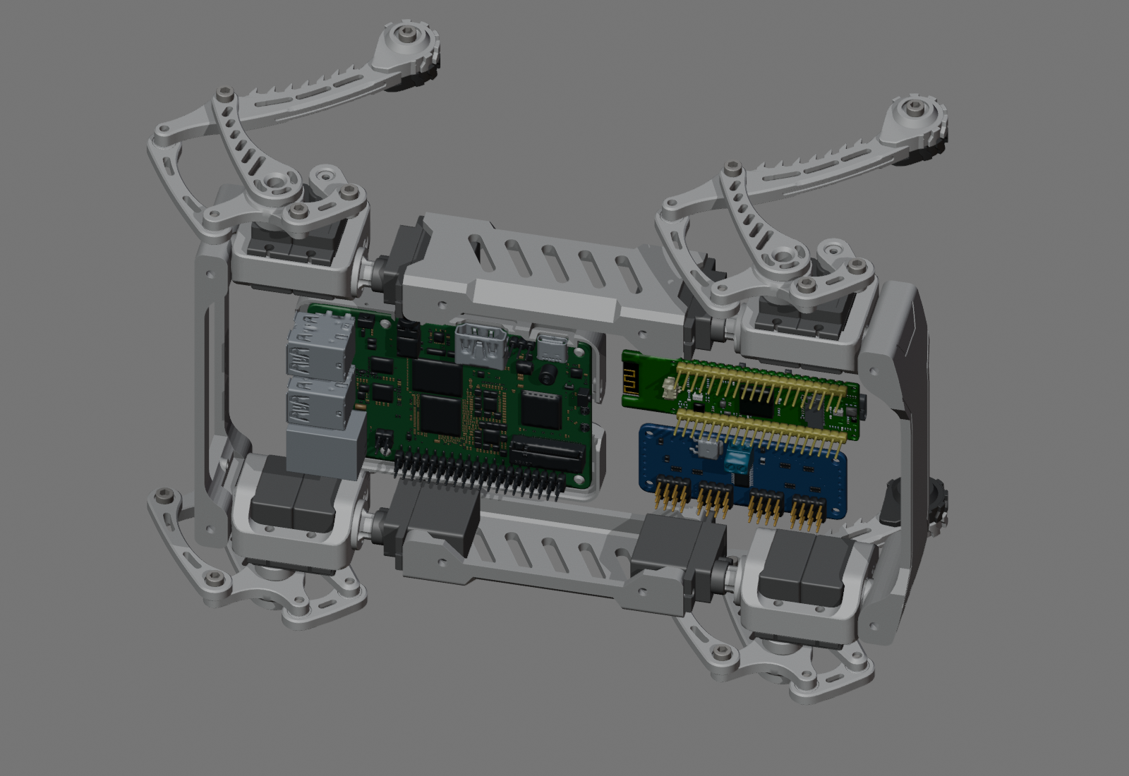
The earlier widened-chassis stage, with the electronics bay open for inspection.
Making room for the electronics#
The first assembly revisions brought the four legs together and fitted the
body’s center mounts and end panels. The electronics then gave the layout a
more concrete set of dimensions to work around.
Three board models are included: a Radxa Dragon Q6A computer, an
ESP32-P4-WIFI6 controller board, and an Adafruit PCA9685 servo-driver
board. The Q6A and PCA9685 came from manufacturer CAD sources; the P4 model was
supplied separately. They were imported at millimeter scale, including the
connectors and components that extend beyond the circuit boards.
The chassis was widened by 40 mm—20 mm on each side. An editable spacing
control moves the leg roots, center mounts, and inserted middle sections of
the front and rear panels together. Existing bearing and screw features retain
their shapes as the width changes.
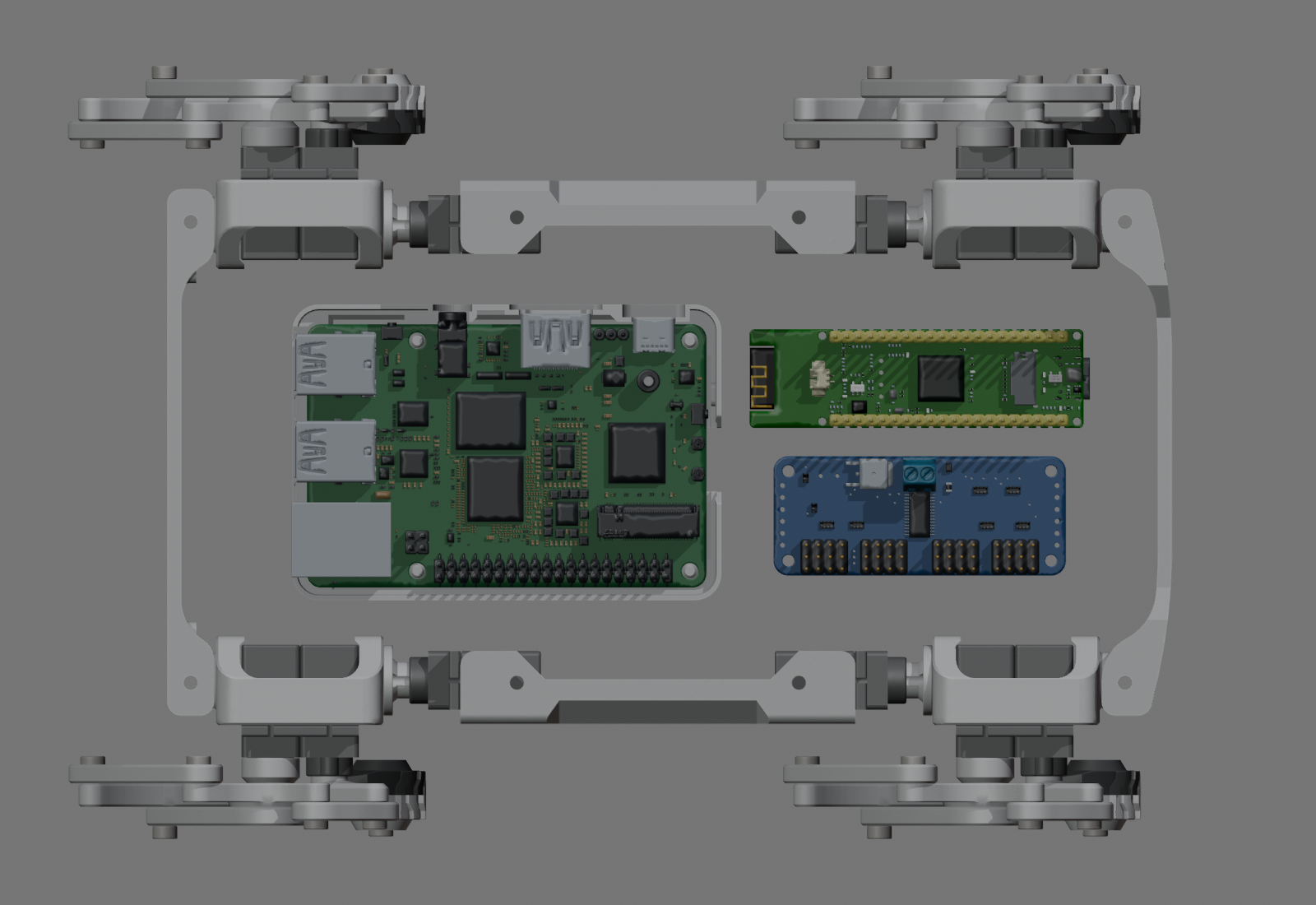
Electronics placement in the widened-chassis revision. The boards are CAD
models; this is not an installed or powered assembly.
The Q6A sits at the front with its ports facing the front panel. The other two
boards sit beside each other toward the rear. The layout includes a Q6A tray,
connector reliefs, and nominal gaps between the board envelopes. Cable plugs,
bend radii, cooling space, and the remaining board fixings still need attention.
Placing a computer in the model does not establish an onboard MetaHuman
installation.
Refining the leg parts as a set#
The upper leg housings have gone through rounded-profile and opening-layout
revisions. After further manual editing, the chosen Part 3 housing and its
editable cutters were synchronized across all four legs. The saved-file report
confirms matching evaluated geometry while preserving the assembly placements.
Earlier housing variants recorded reductions in CAD solid volume, but those
figures belong to those variants. They are not a measured weight saving for
the later manual revision or a printed robot.
The Part 26 linkage also received more clearance and a smoother outline. Its
center first moved 3 mm farther outward, then the concentrated bend became
a broader curve that blends into the round mounting ends. The two oval slots
follow the new outline. The 4 mm plate thickness and functional mounting
geometry were retained.
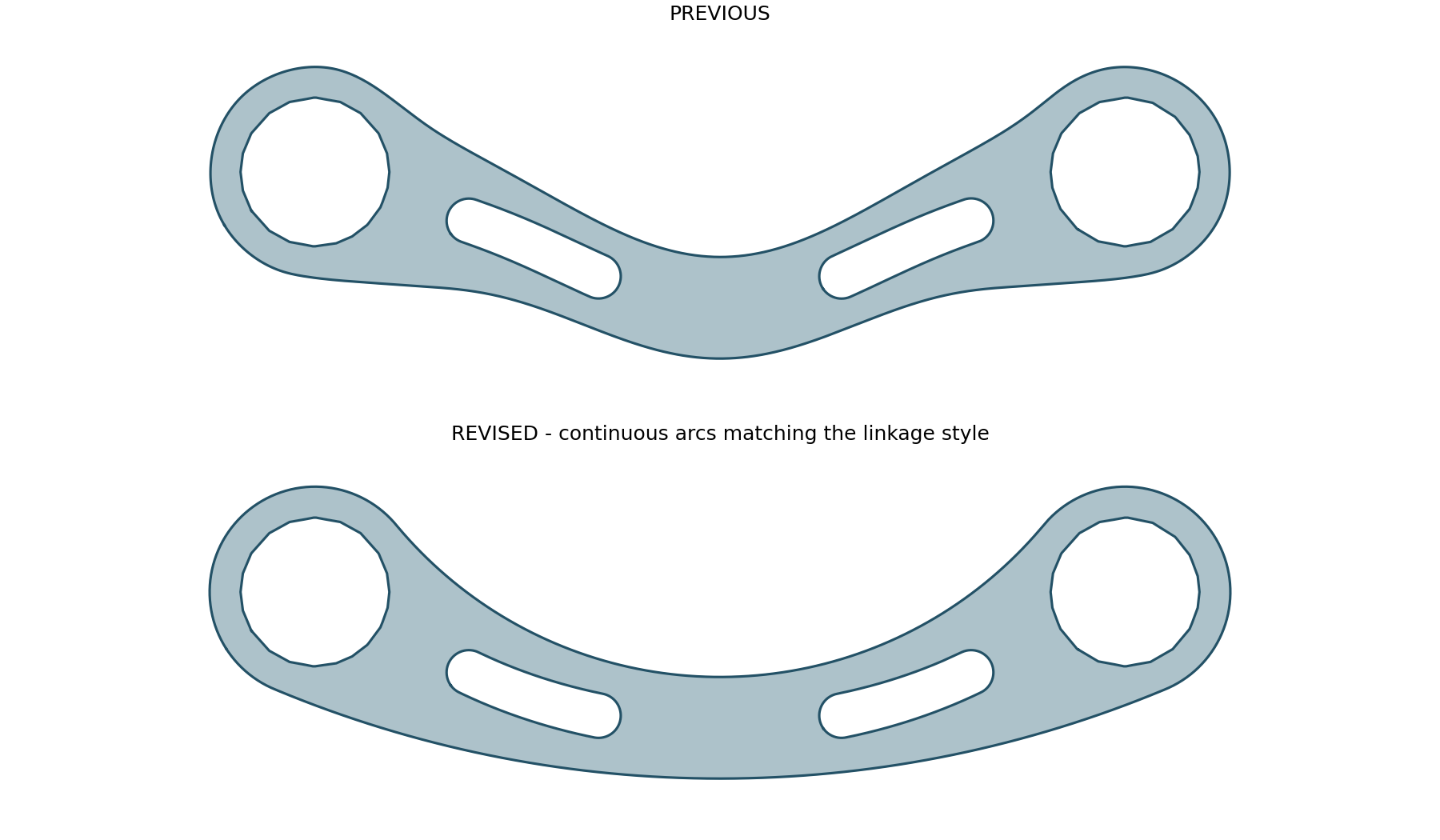
The later curve revision, applied consistently across all four legs. Static
interference checks are recorded; full mechanism travel remains to be tested.
Fitting the front panel around the Q6A#
The front panel now closes around the Q6A’s two USB stacks and Ethernet jack:
three openings serving four USB sockets and one network port. The editable
cutters follow the board, and the panel’s width adjustment was checked at two
settings.
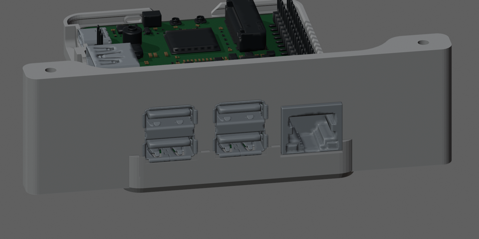
Front-panel revision from the WIP 11 assembly. The existing tray lip remains
visible below the connectors and is still due for trimming.
An internal relief clears the board edge and nearby underside components.
The port openings currently match the modeled connector envelopes without
extra nominal clearance, so manufacturing tolerance and real cable-plug fit
remain open questions. The Q6A tray was deliberately preserved; its front lip
still intersects the panel.
Bringing the covers into the assembly#
WIP 12 added fitted top and bottom covers, each widened from
72 to 112 mm while preserving the original 3 mm plate thickness. Their eight
frame mounting holes align with the current chassis, and both covers follow
the same adjustable width control as the rest of the body.
The saved checks describe closed solids with round hole boundaries retained
and clearance from the board models and servo housings. A small existing height
step in the frame leaves 0.2 mm seating gaps at some mounts. The unchanged Q6A
tray also overlaps the bottom cover, extending the same tray-trimming job
identified at the front panel. Printed fit and strength still need testing.
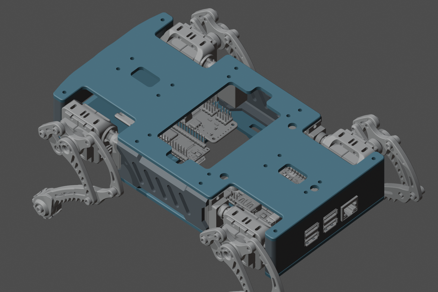
WIP 12: an earlier cover revision, retained here to show how the design changed.
WIP 13 then closed 18 unused openings in the top cover and 15 in the bottom,
including the large access cutouts. Each plate now retains only eight 3 mm
frame screw holes. The 112 mm width, 3 mm base thickness, outer clearance
contours, and bottom tabs were retained. The Q6A tray still needs trimming.
Adding a removable camera and display face#
WIP 14 places a camera above a landscape display on one removable carrier.
The LCD is a Waveshare 2inch LCD Module reference, imported from its official
STEP model. The OV5647 camera reference uses the Arducam B0033 board and
mounting-hole dimensions, with approximate thickness, lens depth, and connector
envelopes. Neither reference establishes the final purchased module or its
electrical compatibility with the V2 controller.
The carrier uses two existing front screw positions on the top cover, adding
3 mm to their stack. The LCD model includes four M2×6 spacers; the camera rests
on four integrated 4 mm standoffs. Final screws, retention hardware, cable
routing, and plug clearance still need to be resolved.
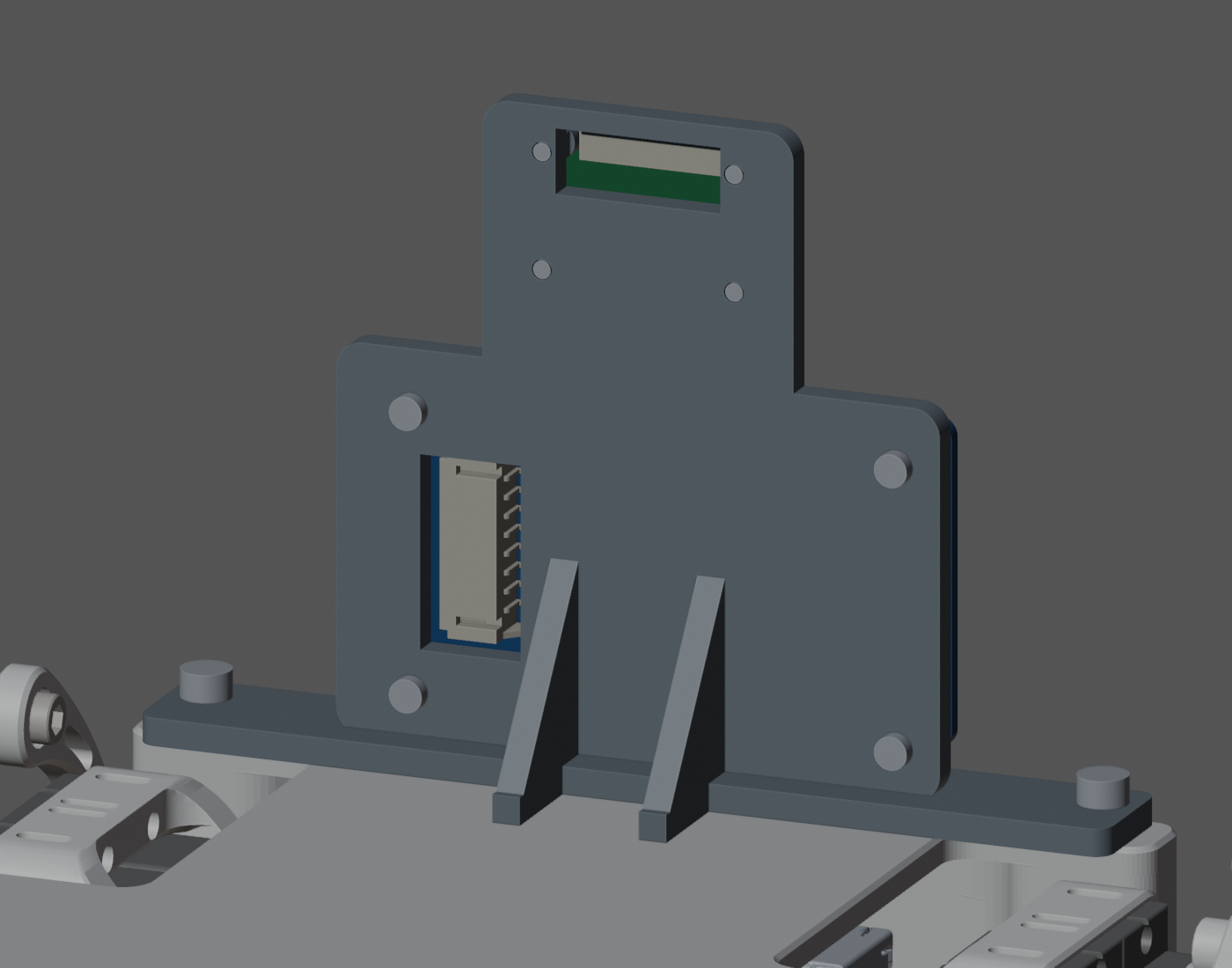
Actual CAD render. Rear cable windows are modeled; the wiring harness is not.
The saved-file report records all 259 existing objects preserved and the new
face geometry checked at two chassis widths. This is saved CAD evidence;
physical fit, optics, cooling, and movement testing remain. The
V2 parts and assembly record
lists the board dimensions, mounting patterns, and component sources.
Keeping the leg research separate#
A parallel study compared three ways to drive a knee with a stationary servo
and short rigid rods. It produced a preferred relay mechanism for further
research, along with pose tests and collision findings. None of the candidates
met the complete requested movement range and pose brief.
That is useful design evidence, but it is a separate research path. The
four-leg assembly shown here should not be read as a validated implementation
of that mechanism. The leg mechanism comparison
records the rod lengths, measured model ranges, rejected poses, and why the
relay variant remains a research testbed.
MetaHuman work has focused on making the existing workflow more consistent.
Follow-up input received while robot or specialist work is pending stays with
the saved request, and input handoffs check that the execution is compatible
with the current software. A successful handoff can report progress without
being mistaken for a missing chat response.
Action-selection refinements separate the next action from the broader goal’s
progress. Invalid model answers return through the existing correction path,
and selected images retain their matching identity and context. Training and
profile-memory reset controls have also received clearer lifecycle handling
and more focused validation.
The September 10 handoff review records 236 passing durable-execution
tests, alongside graph, type, transport, architecture, and isolated-build
checks. Training and reset have their own recorded software and synthetic-data
checks. These are dated development results, not a new physical Ainekio trial
or proof that all current refinements are deployed. The
integration guide explains the workflow they
are improving.
The next checks#
The CAD assembly makes the remaining mechanical questions easier to inspect:
trim the tray and check cover seating, allow for real connectors and cables, check the
complete leg movement range, and print representative joints and mounting
interfaces. Fit, backlash, strength, power demand, and cooling need measurements
on parts and hardware.
This update draws on the September 9–10 Blender revision folders, their READMEs,
saved-file and static-fit reports, and the MetaHuman development ledger.
The mechanical sequence runs from the four-leg layout through the widened
chassis, synchronized housings, smooth linkage, Q6A panel, revised covers, and WIP 14 camera/display carrier. The
MetaHuman checkout was b57d2058 with additional local refinements. Existing
validation records were inspected for this post; mechanical and runtime test
suites were not rerun as part of writing it.